


Chapter 3 63
Utility Procedures
Measuring Swept Return Loss
Chapter 3
Utility Procedures
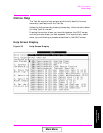
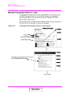
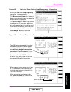
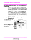
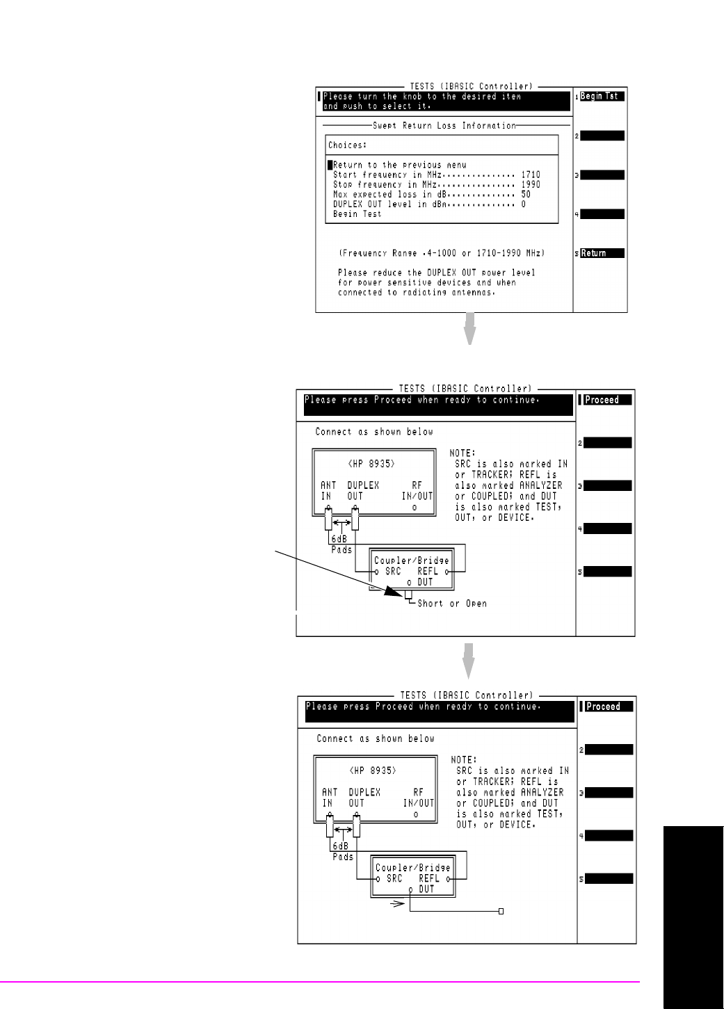
Figure 3-5 Entering Swept Return Loss Measurement Information
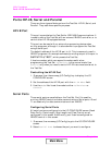
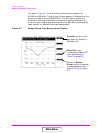
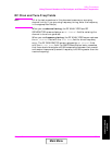
Figure 3-6 Swept Return Loss Measurement Connections
Enter the Start and Stop Frequency
values for the measurement.
The Max expected loss value is used to
determine the graphics scaling when the
measurement is displayed.
The DUPLEX OUT level is adjustable
to reduce the RF level used when mea-
suring the loss of sensitive devices, and
to minimize the amount of transmitted
power during the test (if necessary).
Select Begin Tst (
k1) to continue.
Two 6 dB attenuators (pads), two short
cables, and the return loss bridge are
used to establish a calibration refer-
ence without the device under test
connected. Press Proceed (
k1) to con-
tinue.
As indicated by the NOTE on the
drawing, your return loss bridge may
be marked differently than shown.
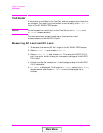
Termination
When measuring the swept return loss
of a transmission line that is not ter-
minated at an antenna, terminate the
line into a 50Ω load.
After connecting your device under
test, press Proceed (
k1) to make the
measurement.
Device under test
Main Menu