


Chapter 2 33
Testing AMPS Base Stations
Compensating for Signal Losses and Gains in the Test Setup
Chapter 2
Testing AMPS Base Stations
Compensating for Signal Losses and Gains in the Test
Setup
Signal losses or gains through cables, splitters, combiners, connectors,
amplifiers, or coaxial switches must be accounted for to ensure
measurement accuracy. These values are entered in the INSTRUMENT
CONFIGURE screen (press the Inst Config key).
Refer to "Measuring Insertion Losses" on page 51 for information about
measuring cable/system losses.
• Total losses/gains between the transmitter’s output and the Test
Set’s RF IN/OUT port are entered in the RF In/Out field. A
negative number (indicating a loss) causes the displayed TX power
measurement to be increased by the entered amount. A positive
number (indicating a gain) causes the RF analyzer to decrease the
displayed TX power measurement by the entered amount.
• Total losses between the Test Set’s DUPLEX OUT port and the base
station’s receive port(s) are entered in the Duplex Out field as a
negative number (such as −1.2). The RF Generator will
automatically increase its level out of the DUPLEX OUT port by the
value entered to compensate for the loss.
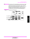
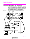
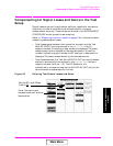
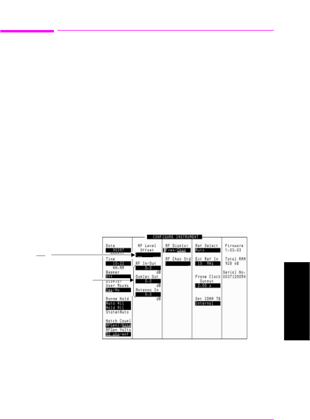
Figure 2-2 Entering Test System Losses and Gains
On/Off
Set the RF Level Offset
field to On.
Enter the loss or gain
between each port and the
base station.
LS AMPS
Main Menu