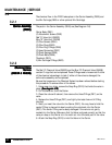
FOAMPRO® F1000
16
©2001 R11.01
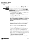
STARTUP | CALIBRATION
2.2
NONO
NONO
NO
TE:TE:
TE:TE:
TE:
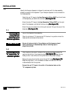
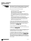
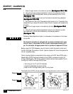
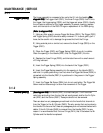
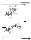
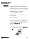
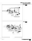
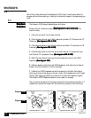
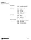
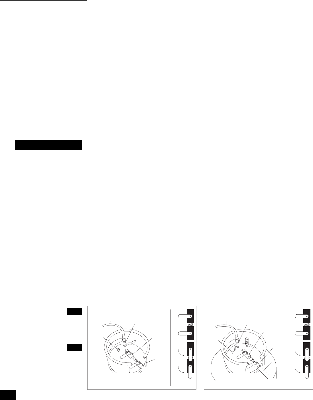
1 - Close nitrogen valve on the chemical cylinder.
(See diagrams 16A & 16B)(See diagrams 16A & 16B)
(See diagrams 16A & 16B)(See diagrams 16A & 16B)
(See diagrams 16A & 16B)
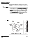
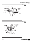
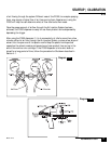
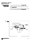
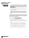
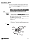
2 - Using the nitrogen pressure adjustment valve for the chemical cylinder
being adjusted, turn the adjustment valve counterclockwise two full turns.
(See diagram 17A)(See diagram 17A)
(See diagram 17A)(See diagram 17A)
(See diagram 17A)
3 - Locate the pressure relief valve on the chemical cylinder being adjusted.
(See diagrams 16A & 16B)(See diagrams 16A & 16B)
(See diagrams 16A & 16B)(See diagrams 16A & 16B)
(See diagrams 16A & 16B)
4 - Pull upward on the ring of the pressure relief valve for 2 or 3 seconds, then
release the ring to allow the valve to close. A burst of pressure will escape from
the valve.
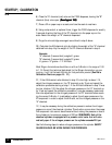
5 - Open the nitrogen valve on the chemical cylinder.
(See diagrams 16A &(See diagrams 16A &
(See diagrams 16A &(See diagrams 16A &
(See diagrams 16A &
16B)16B)
16B)16B)
16B)
6 - Using the nitrogen pressure adjustment valve for the chemical cylinder
being adjusted, turn the valve clockwise to the desired pressure.
(See diagram 17A)(See diagram 17A)
(See diagram 17A)(See diagram 17A)
(See diagram 17A)
Following these steps should result in a decrease in the pressure on the chemi-
cal cylinder.
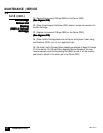
The chemical cylinders are equipped with a pressure overload relief valve
that will open if the pressure of the cylinder exceeds approximately 220
psi. Do not adjust nitrogen pressure on the cylinders to approach 220 psi.
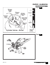
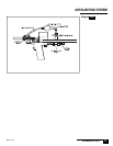
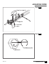
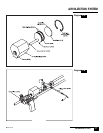
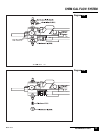
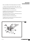
Before using the F1000 dispenser, you will need to install the plastic nozzle onto
the Mix Cartridge. The valves on the Air Injection System will have to be opened so
that air is passing freely.
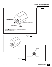
The Air Injection System is comprised of two valves, an On/Off Valve (D704) and a
Needle Valve (D703) that are connected to the F1000 by a series of simple 1/8”
fittings. (See Diagram 17B) The Air Injection System serves three purposes. The air
flowing into the Mix Cartridge (D603) helps:
• the mixing of the “A” and “B” chemicals
• propel the chemicals out of the nozzle,
• keep the Mix Cartridge (D603) clear of curing foam.
The Needle Valve (D703) can be adjusted by turning the knob to control the amount
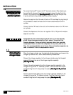
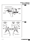
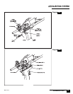
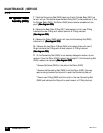
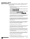
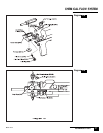
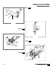
Nitrogen
Supply
Hose
Nitrogen
Valve
Pressure
Relief
Valve
Cylinder
Chemical
Valve
Hose Filter
Chemical
Valve
Cylinder Valves - 17 Gal.
Closed
Open
Chemical
Valve
Positions:
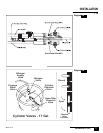
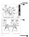
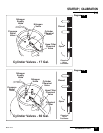
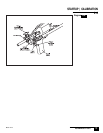
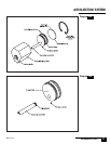
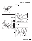
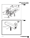
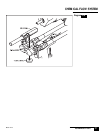
Nitrogen
Supply
Hose
Nitrogen
Valve
Pressure
Relief
Valve
Cylinder
Chemical
Valve
Hose Filter
Chemical
Valve
Cylinder Valves - 60 Gal.
Closed
Open
Chemical
Valve
Positions:
Chemical
Filter
Diagram 16A
Diagram 16B
(Left)
(Right)