FOAMPRO® F1000
8
©2001 R11.01
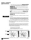
2 | Turn on the air supply to the dispenser, and check for leaks.
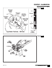
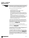
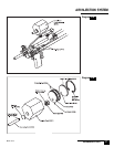
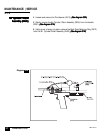
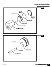
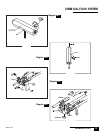
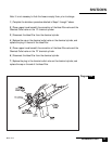
3 | Remove Mix Cartridge Plug (D620) if one is in place
. .
. .
. Do not install nozzle
until calibration steps are completed.
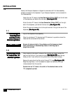
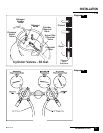
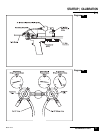
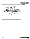
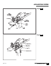
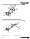
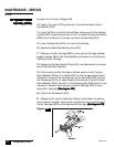
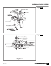
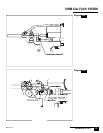
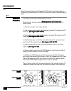
4 | Open both of the air injection valves (D704, D705)
(See diagram 9A)(See diagram 9A)
(See diagram 9A)(See diagram 9A)
(See diagram 9A) to see
if the air passes freely through the dispenser. Re-close both of the air injection
valves, as they must be closed to complete the calibration of the dispenser.
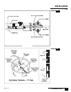
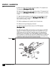
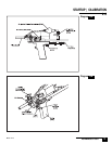
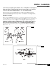
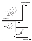
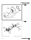
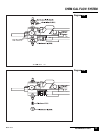
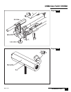
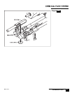
5 | Turn the adjustment valves on both nitrogen regulators leading to the "A"
chemical and the "B" chemical counterclockwise two full turns.
(See diagram(See diagram
(See diagram(See diagram
(See diagram
9B)9B)
9B)9B)
9B)
6 | Open the valve on top of the nitrogen cylinder, and check for leaks.
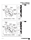
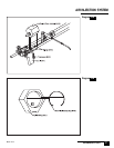
7 | Adjust the "A" component nitrogen regulator (one with the red hose) to 190
psi (starting point) by turning clockwise
(See diagram 9B)(See diagram 9B)
(See diagram 9B)(See diagram 9B)
(See diagram 9B)
8 | Adjust the "B" component nitrogen regulator (one with the blue hose) to
140 psi (starting point) by turning clockwise
(See diagram 9B)(See diagram 9B)
(See diagram 9B)(See diagram 9B)
(See diagram 9B)
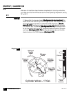
The chemical cylinders are equipped with a pressure overload relief valve
that will open if the pressure of the cylinder exceeds approximately 220
psi. Do not adjust nitrogen pressure on the chemical cylinders to approach
220 psi.
NONO
NONO
NO
TE:TE:
TE:TE:
TE:
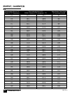
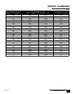
STARTUP | CALIBRATION
2.1