FOAMPRO® F1000
6
©2001 R11.01
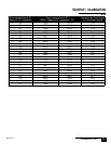
STARTUP | CALIBRATION
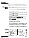
2.0
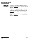
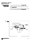
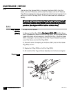
Make sure all installation steps have been completed prior to startup and calibra-
tion. Make sure that the chemicals are at the correct operating temperature, usually
70° to 90° F.
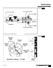
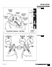
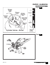
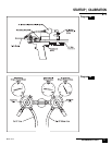
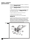
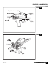
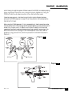
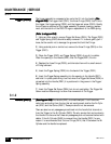
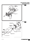
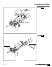
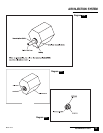
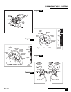
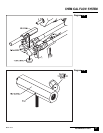
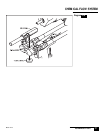
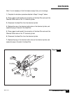
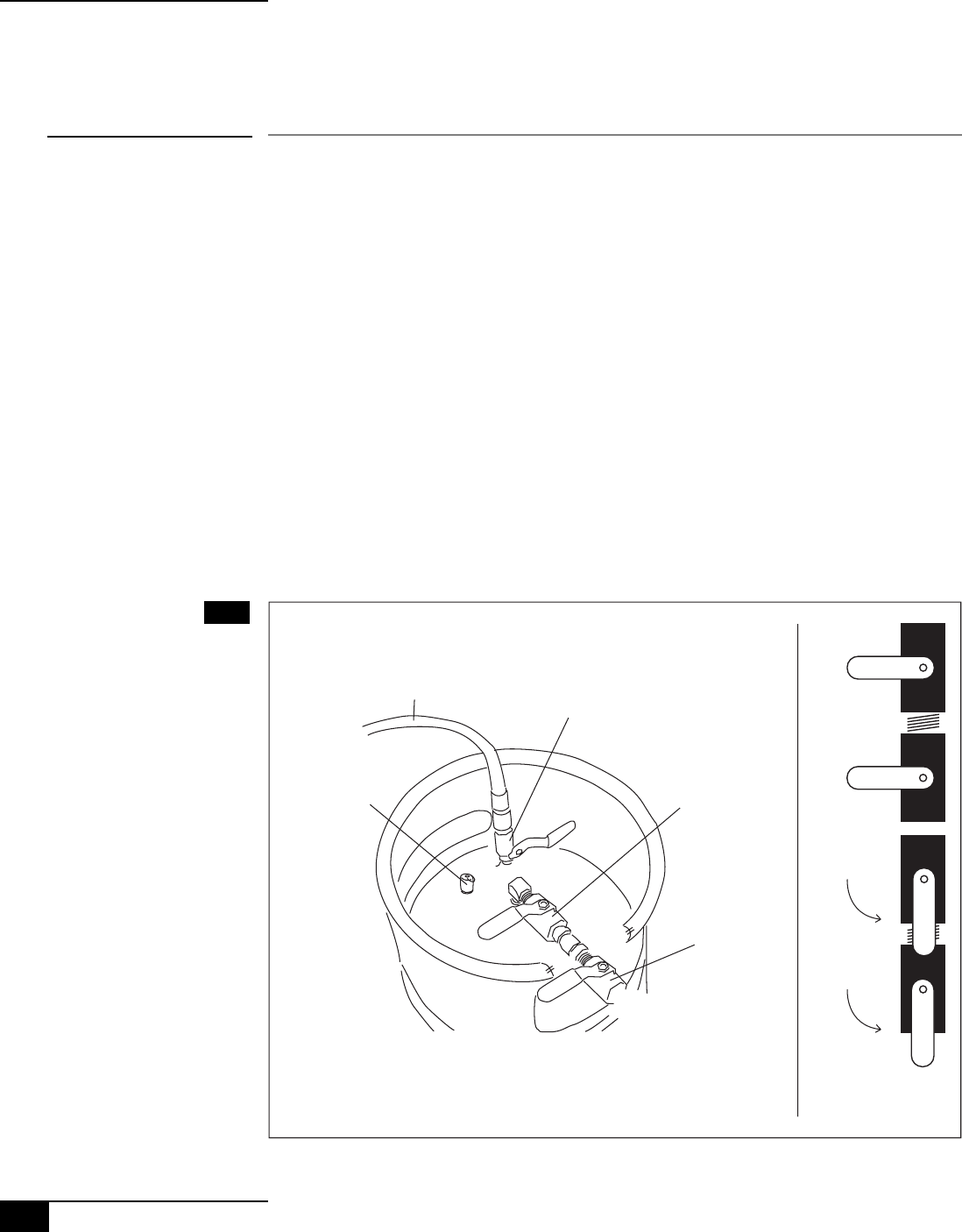
1 | Be sure that all valves are closed.
(See diagrams for valve locations)(See diagrams for valve locations)
(See diagrams for valve locations)(See diagrams for valve locations)
(See diagrams for valve locations) This
would include: The valve on top of the nitrogen cylinder. The nitrogen valve on
top of both chemical cylinders ("A" Chemical and "B" Chemical).
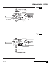
(See dia-(See dia-
(See dia-(See dia-
(See dia-
grams 6A & 7A)grams 6A & 7A)
grams 6A & 7A)grams 6A & 7A)
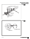
grams 6A & 7A) The chemical outlet valve on top of both chemical cylinders
("A" chemical and "B" chemical)
(See diagrams 6A & 7A)(See diagrams 6A & 7A)
(See diagrams 6A & 7A)(See diagrams 6A & 7A)
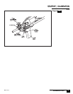
(See diagrams 6A & 7A) The chemical valve
on the filter end of both the red "A" component hose and the blue "B" compo-
nent hose.
(See diagram 6A & 7A)(See diagram 6A & 7A)
(See diagram 6A & 7A)(See diagram 6A & 7A)
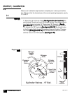
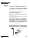
(See diagram 6A & 7A) Both the red chemical valve and the blue
chemical valve on the F1000 dispenser
(See diagram 7B).(See diagram 7B).
(See diagram 7B).(See diagram 7B).
(See diagram 7B).
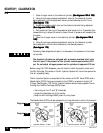
Startup:Startup:
Startup:Startup:
Startup:
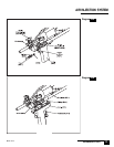
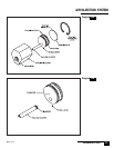
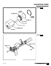
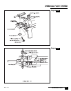
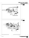
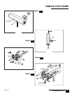
2.1
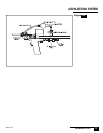
Nitrogen
Supply
Hose
Nitrogen
Valve
Pressure
Relief
Valve
Cylinder
Chemical
Valve
Hose Filter
Chemical
Valve
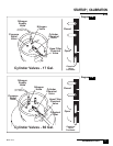
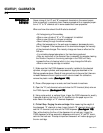
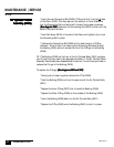
Cylinder Valves - 17 Gal.
Closed
Open
Chemical
Valve
Positions:
Diagram 6A