FOAMPRO® F1000
38
©2001 R11.01
3.2
MAINTENANCE | SERVICE
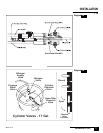
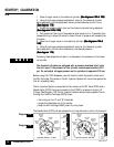
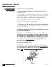
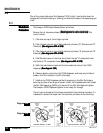
Before performing any service work on the F1000 it is CRITICAL that all pressure of
the Chemical Flow System is relieved. Complete the following steps to relieve
pressure on the F1000.
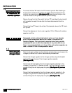
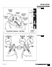
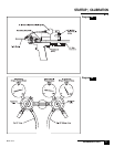
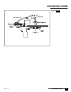
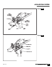
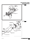
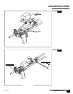
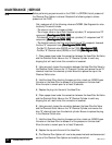
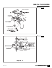
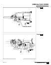
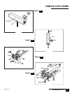
First, make sure all of the following valves are CLOSED. (See Diagrams for valve
locations) This would include:
- The valve on top of the nitrogen cylinder
- The nitrogen valve on top of both chemical cylinders (“A” component and “B”
component)
(See diagrams 39A & 39B)(See diagrams 39A & 39B)
(See diagrams 39A & 39B)(See diagrams 39A & 39B)
(See diagrams 39A & 39B)
-The chemical valve on top of both chemical cylinders (“A” component and “B”
component)
(See diagrams 39A & 39B)(See diagrams 39A & 39B)
(See diagrams 39A & 39B)(See diagrams 39A & 39B)
(See diagrams 39A & 39B)
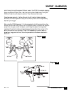
- The chemical valve on the filter end of both the red “A” component hose and
the blue “B” component hose.
(See diagrams 39A & 39B)(See diagrams 39A & 39B)
(See diagrams 39A & 39B)(See diagrams 39A & 39B)
(See diagrams 39A & 39B)
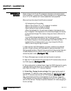
-The Red “A” Chemical valve (D503R) on the F1000
(See diagram 39A)(See diagram 39A)
(See diagram 39A)(See diagram 39A)
(See diagram 39A)
-The Blue “B” Chemical valve (D503B) on the F1000
(See diagram 39A)(See diagram 39A)
(See diagram 39A)(See diagram 39A)
(See diagram 39A)
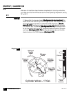
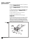
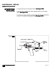
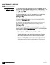
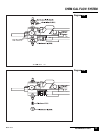
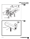
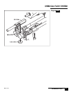
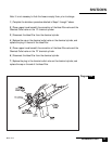
1 | Place a paper towel under the connection between the Hose Filter End Valve
and the Chemical Outlet Valve on the “A” Chemical Cylinder to catch any
dripping that will result when this connection is loosened.
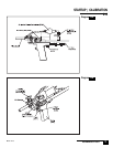
2 | Using a wrench, loosen the connection between the Hose Filter End Valve to
the Chemical Outlet Valve on the “A” Chemical Cylinder, and remove the red “A”
chemical hose from the chemical cylinder. Be sure to replace the cap on the
Chemical Outlet valve.
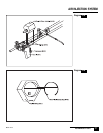
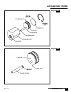
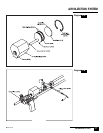
3 | Hold the Hose Filter, directing the open end into a trash can. SLOWLY open
the valve on the Hose Filter to release all of the pressure on the hose itself.
Allow the valve to remain open for at least 30 seconds.
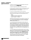
4 | Replace the plug into the end of the Hose Filter.
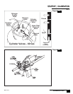
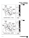
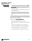
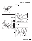
5 | Place a paper towel under the connection between the Hose Filter End Valve
and the Chemical Outlet Valve on the “B” Chemical Cylinder to catch any
dripping that will result when this connection is loosened.
6 | Using a wrench, loosen the connection between the Hose Filter End Valve
and the Chemical Outlet Valve on the “B” Chemical Cylinder, and remove the
blue “B” chemical hose from the chemical cylinder. Be sure to replace the plug
in the Chemical Outlet valve
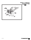
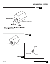
7 | Hold the Hose Filter, directing the open end into a trash can. SLOWLY open
the valve on the Hose Filter to release all of the pressure on the hose itself.
Allow the valve to remain open for at least 30 seconds.
8 | Replace the cap onto the end of the Hose Filter.
9 | The Chemical Flow System will now be de-pressurized and maintenance and
service of the Chemical Flow System can be safely carried out.