FOAMPRO® F1000
24
©2001 R11.01
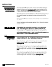
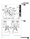
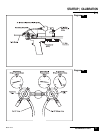
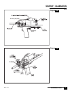
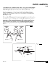
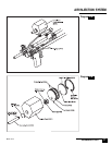
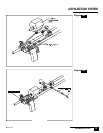
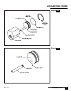
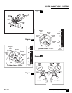
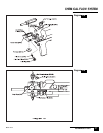
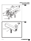
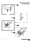
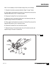
The trigger assembly is composed of six parts that fit into the handle:
(See(See
(See(See
(See
diagram 25A)diagram 25A)
diagram 25A)diagram 25A)
diagram 25A). The trigger itself (D301), the three O rings (D303) that fit onto
the trigger, the trigger spring (D302), and the trigger set screw (D304). Usually
the only service required of the trigger assembly is general cleaning, replace-
ment and lubrication of the D303 O rings or replacement of the D302 spring.
(Refer to diagram 25A)(Refer to diagram 25A)
(Refer to diagram 25A)(Refer to diagram 25A)
(Refer to diagram 25A)
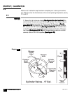
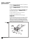
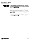
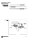
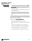
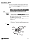
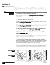
1 | Using an Allen wrench, remove Trigger Set Screw (D304). The Trigger (D301)
and Trigger Spring (D302) should be easily removed. If it is stuck, gently pull it
loose, but be careful not to damage the grooves that hold the O rings.
2 | Using a dental pick or similar tool, remove the three O rings (D303) on the
Trigger (D301).
3 | Clean the Trigger (D301) and Trigger Spring (D302) of any dirt or debris.
Clean the opening in the Handle (D201) that the Trigger(D301) fits into.
4 | Replace the three O rings (D303), and lubricate them with a small amount
of O ring lubricant.
5 | Insert the Trigger Spring (D302) into the back of the Trigger (D301).
6 | Insert the Trigger/Spring assembly into the opening in the Handle (D201),
and hold it in place, positioning it so that when the Trigger Set Screw (D304) is
reinserted into the Handle (D201) it is positioned in the groove in the Trigger/
Spring assembly.
7 | Insert the Trigger Set Screw (D304), but do not overtighten. The Trigger Set
Screw must be loose enough to allow free movement of the Trigger.
MAINTENANCE | SERVICE
Handle (D20Handle (D20
Handle (D20Handle (D20
Handle (D20
1)1)
1)1)
1)
3.1.2
(See diagram 25B)(See diagram 25B)
(See diagram 25B)(See diagram 25B)
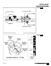
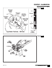
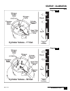
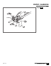
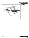
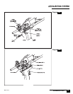
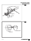
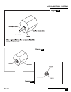
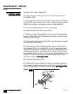
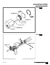
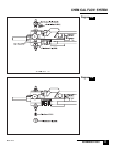
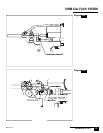
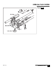
(See diagram 25B) The Handle (D201) is a machined part. It will have two
metal pins protruding from the top that act as alignment aids for the Air Cylin-
der (D401) and the Carrier (D501). These pins should not be removed.
There are also two air passageways machined into the handle that channel air
from the Trigger to the Air Cylinder (D400). The only service that can be done to
the Handle is to be sure that these air passageways do not become blocked with
debris. If the Air Cylinder (D400) is removed from the Handle (D201) for any
reason it is recommended that the two O rings (D414) that fit between the Air
Cylinder and the Handle be replaced.
3.1.1
TT
TT
T
rigger (D300)rigger (D300)
rigger (D300)rigger (D300)
rigger (D300)