


Rockwell Automation Publication 150-QS003D-EN-P - November 2013 15
Installation Chapter 2
Use of Power Factor Connection Capacitors (PFCCs)
SMC-50 controllers can be installed in a system with PFCCs. The PFCCs must
only be located on the line side of the controller. Placing the PFCCs on the
load side of the SMC will result in damage to the SCRs in the SMC-50. For
additional details, see the user manual.
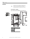
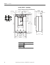
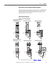
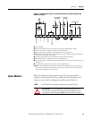
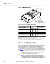
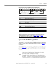
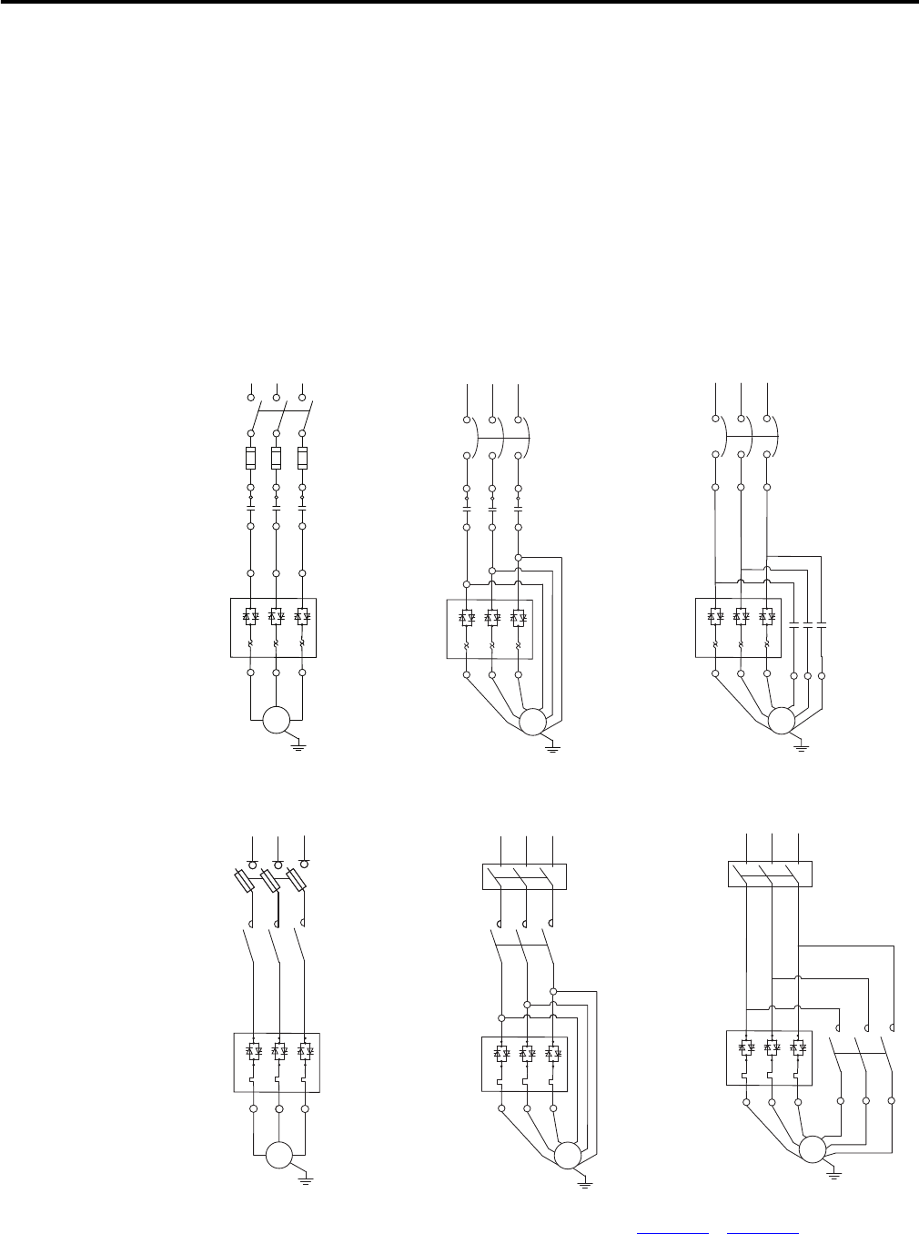
Typical Power Diagrams
Figure 8 - Power Wiring Diagrams
For wiring examples with bypass, please see Figure 19 …Figure 21.
Diagrams per NEMA Symbology
Line Connection with
Isolation Contactor, Default Mode
SMC-50
Motor
T1 T2 T3
K1
L1 L2 L3
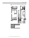
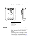
Inside the Delta Connection with
Isolation Contactor, Optional Mode
K1
L1 L2
L3
T4
T5
SMC-50
Delta Connection with Shorted
SCR Protection, Optional Mode
SMC-50
L1
L2
L3
K1
Motor
T1
T2 T3
T4
T5
T6
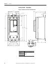
Delta Connection with Shorted
SCR Protection, Optional Mode
Inside the Delta Connection with
Isolation Contactor, Optional Mode
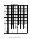
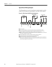
Diagrams per IEC Symbology
Line Connection with
Isolation Contactor, Default Mode
SMC-50
L1 L2 L3
1
35
2 4
6
1
35
SMC-50
2
4
6
W
1
U
1
3~
M
1
35
L1 L2 L3
1
35
2 4
6
1
35
2 4
6
K1
W
2
U
2
V
2
SMC-50
3
M
~
L1 L2 L3
1
35
1
35
2 4
6
2 4
6
1
35
4
V
6
W
2
U
K1
V
1
2
4
6
W
1
U
1
3~
M
V
1
2 4
6
WU
V
K1
1
35
22
2
T1
T2 T3
Motor
T6