


Rockwell Automation Publication 150-QS003D-EN-P - November 2013 37
Programming Chapter 3
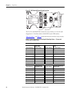
The following tables define the functions for the three banks of ON/OFF
8-switch DIP switches. Each of the three banks is defined by a high level,
functional name with each switch having a unique function.
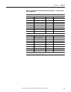
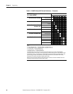
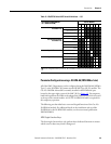
Table 13 - ON/OFF 8-Switch DIP Switch Definitions — Device
DEVICE Configuration Bank
(O = Switch OPEN)
Switch Number
#1 #2 #3 #4 #5 #6 #7 #8
Starting Mode—
Controller Parameter
49
Linear Speed Acceleration (default) 0 0
Current Limit 0 1
Soft Start 1 0
Pump Start 1 1
Stop Mode ➊➋—
Controller Parameter
65
Linear Speed Deceleration (default)
00
Soft Stop 01
Braking 10
Pump Stop 11
Energy Saver ➌—
Controller Parameter
193
Enable
1
Disable (default) 0
Braking Current —
Controller Parameter
69
50% 000
100%
001
150%
010
200% (default) 011
250%
100
300%
101
350% 110
400%
111
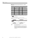
➊ When the Stop Mode is configured as (a) Linear Speed Decel, (b) Soft Stop, (c) Pump Stop, and the
Stop Time (rotary switch S4) is set to zero, a Coast stop will result. A non-zero Stop Time value for
the three previously listed Stop Modes defines the time to stop period which is based on that
specific configuration.
➋ If the Stop Mode is configured as Braking, then the Stop Time setting (Rotary Switch S4) is used to
select either the Automatic Zero Speed Detection method (Stop Time is set to zero) or the Timed
Brake method (Stop Time is not set to zero).
➌ With the Energy Saver switch (#5) set to ENABLE, the Energy Saver Level, Parameter 193, is
automatically configured by the PCM to 0.25.
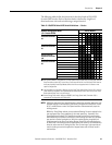
NOTE: 1 With the Automatic Zero Speed Detection method, the controller applies the user-
selected Braking Current defined by the Device Configuration Switch Bank. Switch
#6, #7, and #8 senses a motor Zero Speed condition and automatically stops the
braking process.
2 With the Timed Brake method, the user-selected Braking Current is applied for the
user-configured Stop Time regardless of the motor speed (e.g., Automatic Zero
Speed Detection disabled). The Timed Brake method can be used in applications
where detecting zero speed is ineffective or when braking the motor to a complete
stop results in random overload trips. With this method, braking is applied for a
fixed time equal to the Stop Time setting (Rotary Switch S4) and multiplied by ten.
An ideal Stop Time setting can be accomplished by trial and error, but should always
allow for some coast time. Setting the Stop Time for too long of a time period can
result in braking current to be applied to a stopped motor and will likely result in
overload trips.