


34 Rockwell Automation Publication 150-QS003D-EN-P - November 2013
Chapter 3 Programming
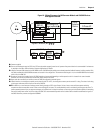
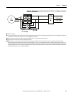
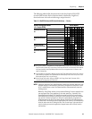
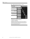
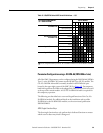
Figure 22 - DIP Switch & Rotary Switch Locations
The Cat. No. 150-SM6 PCM contains five rotary switches, S1…S5, each with
designations 0…F and three banks of ON/OFF 8-switch DIP switches.
Tab le 1 0
, Table 11, and Tabl e 12 define the functions of the five rotary switches.
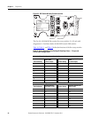
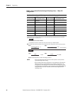
Table 10 - Rotary Switch Position Settings & Resulting Values — Torque and
Current Limit Configurations
S1 = Initial Torque Configuration — Controller Parameter 51
Position Setting
Resulting Initial
Torque Value
[% motor torque] Position Setting
Resulting Initial Torque
Value
[% motor torque]
010 858
116 964
2 22 A 70 (default)
328 B76
434 C82
540 D88
646 E94
7 52 F 100
S2 = Current Limit Configuration — Controller Parameter 53
Position Setting
Resulting Current
Limit Value [% FLC] Position Setting
Resulting Current Limit
Value [% FLC]
0 200 8 360 (default)
1 220 9 380
2 240 A 400
3 260 B 420
4 280 C 440
5 300 D 460
6 320 E 480
7 340 F 500
S1
S1
0
F
E
D
C
B
A
9
8
7
6
5
4
3
2
1
0
F
E
D
C
B
A
9
8
7
6
5
4
3
2
1
0
F
E
D
C
B
A
9
8
7
6
5
4
3
2
1
0
F
E
D
C
B
A
9
8
7
6
5
4
3
2
1
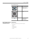
CAT.
150-SM6
SER.
A
SMC-50 PARAMETER CONFIGURATION
S1 Initial Torque
S2 Current Limit
S3 Ramp Time
S4 Stop Time
S5 Motor FLC
MFC LOC MFG DATE
FACxx yy/mm/dd
S4
S4
S3
S3
S2
S2
OPEN
OPEN
1 2 3 4 5 6 7 8
1 2 3 4 5 6 7 8
OPEN
OPEN
1 2 3 4 5 6 7 8
1 2 3 4 5 6 7 8
OPEN
OPEN
1 2 3 4 5 6 7 8
1 2 3 4 5 6 7 8
I/O
I/O
I/O
I/O
DEVICE
DEVICE
DEVICE
DEVICE
PROTECTION
PROTECTION
PROTECTION
PROTECTION
0
F
E
D
C
B
A
9
8
7
6
5
4
3
2
1
S5
S5
Rotary Switch
DIP Switch
Diagnostic
LEDs