


Rockwell Automation Publication 150-QS003D-EN-P - November 2013 39
Programming Chapter 3
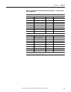
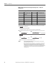
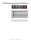
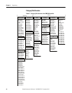
Table 15 - ON/OFF 8-Switch DIP Switch Definitions — I/O
Parameter Configuration using a 20-HIM-A6 (FRN1.006 or later)
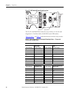
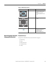
All of the SMC-50 parameters can be configured using the 20-HIM-A6 (NEMA
Type 1) or the 20-HIM-C6S (remote-mount NEMA Type 4X/12) module. The
Cat. No. 20-HIM-A6 module is normally installed in the HIM bezel/port
located in the upper right corner of the SMC-50 (See Figure 12
). For temporary
hand-held operation, the HIM can be plugged into DPI Port #2, which is located
at the top of the control module. A Cat. No. 20-HIM-H10 cable is required for
this temporary operation.
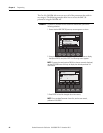
The following text describes basic screen and keypad functions of the Cat. No.
20-HIM-A6 module. For additional detail on the installation and use of the
20-HIM-A6 or the 20-HIM-C6S modules, see the user manual, publication
20HIM-UM001.
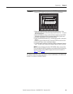
HIM Single-Function Keys
The four single-function keys only perform their dedicated functions no matter
which screen or data entry mode is being used.
I/O Configuration ➊ Bank
(O = Switch OPEN)
Switch Number
#1 #2 #3 #4 #5 #6 #7 #8
Aux #1 Configuration
Parameter 172
Normal (default) 0 0
Up-to-Speed (UTS) 0 1
Fault 1 0
Alarm 1 1
Aux #2 Configuration
Parameter 176
Normal 00
UTS 01
Fault 10
Alarm 11
Input #1 Parameter 56 Start/Coast (default) 0
Start/Stop Option 1
Input #2 Parameter 57 Stop Option (default) 00
Clear Fault 01
Slow Speed 10
Fault 11
➊ The I/O Configuration ability of the Cat. No. 150-SM6 is limited to the Control Module’s standard
I/O.