


18 Rockwell Automation Publication 150-QS003D-EN-P - November 2013
Chapter 2 Installation
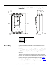
Typical Control Wiring Examples
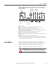
The following figures are control wiring diagram examples using the controller
standard I/O. For additional wiring examples, see the SMC-50 User Manual.
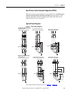
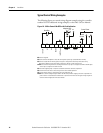
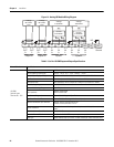
Figure 10 - 2-Wire Control (No DPI) with Fault Indication
➊ Customer supplied.
➋ See the controller nameplate to verify the control power input ratings (120V/240V AC or 24V DC).
➌ Terminal 10 (In2) 24V DC normally open (N.O.) input is configured for Start/Stop or Start/Coast using
Parameter 57. When using the Start/Stop or Start/Coast, the N.O. contact must be used.
NOTE: The controller will generate an I/O configuration fault if any input is configured for START or SLOW speed
and no input is configured for COAST or STOP.
➍ A customer-supplied jumper is required to enable the controller’s standard I/O operation.
➎ The terminal must be wired to the control ground to ensure reliable operation.
➏ The Aux2 output contact is configured for Fault using Parameter 176.
NOTE: Due to current leakage through an SCR in the OFF state (controller stopped), some form of upstream line
power isolation is recommended if maintenance is required on the motor. See the typical wiring diagram for
Isolation Contactor Application in the User Manual.
Start/Stop
3
1
Indication LED
1
-L2
+L1
6
Control
Ground
5
2
-L2 +L1
Intl +24V DC
In1 DC
In2 DC
Enable I/O
Intl DC Common
Aux 2
Aux 1
-L2 +L1
12
11
10 9
8
7
65
4
32
1
4
Control Power