


30 Rockwell Automation Publication 150-QS003D-EN-P - November 2013
Chapter 2 Installation
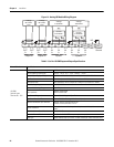
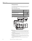
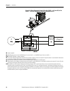
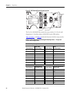
Figure 20 - Wiring Diagram for Frame C (Cat. No. 150-SC…) or Frame D (Cat. No.
150-SD…) Devices with Bypass Contactor and Bypass Bus Kit
➊
Customer supplied.
➋ SMC-50 Bypass bus kit Cat. No. 150-SCBK (Frame C; Cat. No. 150-SC…) or 150-SDBK (Frame D; Cat. No. 150-SD…).
NOTE: Controller FRN 3.001 or higher is required.
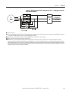
➌ Due to current leakage through an SCR in the OFF state (controller stopped), some form of upstream line power isolation is recommended if maintenance
is required on the motor. See the Isolation Contactor Applications for details.
➍ Bypass must be controlled by an auxiliary contact of the SMC-50 that is configured for external bypass.
➎ In North America, size the bypass contactor per the motor Hp and FLA. In IEC applications, size the bypass contactor per the motor AC-1 rating. The short-
circuit rating of the bypass contactor must be similar to that of the SMC-50.
NOTE: In addition to a small amount of leakage current flowing through an SCR in the off-state, failure of one or more solid-state power switching
components allows uncontrolled current to flow to the winding(s) of the motor. This could potentially result in overheating or damage to the motor. To
prevent potential personal injury or equipment damage, the installation of an isolation contactor or shunt trip-type circuit breaker capable of interrupting
the motor’s locked rotor current on the line side of the SMC-50 is recommended. Operation of the isolation device should be coordinated using one of
the SMC-50 auxiliary contacts configured to NORMAL.
T1/2
T2/4
T3/6
L1/1
L2/3
L3/5
SMC-50
3-Phase AC
Line Power
Circuit
Protective
Device
Bypass Contactor (BC)
M
2
1
1
1
3
4
5
2