


22 Rockwell Automation Publication 150-QS003D-EN-P - November 2013
Chapter 2 Installation
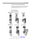
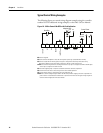
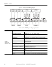
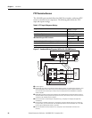
Figure 14 - Analog I/O Module Wiring Diagram
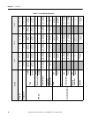
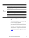
Table 6 - Cat. No. 150-SM3 Input and Output Specifications
V / I
OUT
1+
Output #1
Voltage
or Current
Load
V / I
OUT
1-
B1
+
-
B2
V / I
OUT
2+
Output #2
Voltage
or Current
Load
V / I
OUT
2-
B3
+
-
B4
V
IN
1+
I
IN
1+
V / I
IN
1-
Input #1
Voltage
Transmitter
or
Current
Transmitter
B5
+
B6
-
B7
V
IN
2+
I
IN
2+
V / I
IN
2-
Input #2
Voltage
Transmitter
or
Current
Transmitter
B8
+
B9
-
B10
NC
NC
Control
Ground
B11 B12
Control Circuit Specification
150-SM3
Optional inputs:
Terminals B5…B10
Number of Inputs 2 differential inputs
Normal Operating Input Ranges ±10V, 0…10V, 0…5V, 1…5V, 0…20 mA, 4…20 mA
Full Scale Operating Input Ranges ±10.5V, 0…10.5V, -0.5…5.25V, 0.5…5.25V, 0…21 mA, 3.5…21 mA
Input Resolution 16 bit (sample rate = 60 Hz)/13 bit (sample rate = 250 Hz)
Data Refresh Rate: Filter dependent: 100 ms (sample rate = 60Hz);24 ms (sample rate = 250Hz)
Rated Working Voltage 24V DC / 17V AC
Common Mode Voltage Range ±10V DC / channel
Input Impedance
220 kΩ: voltage mode
249 Ω: current mode
Input Channel Diagnostics Over and Under Range and Open Circuit
Open Circuit Detection Time Positive Full Scale Reading: within 3 seconds (max)
Maximum Overload at Input Terminals
Voltage: ±24V DC continuous at 0.1 mA
Current: ±30 mA continuous at 7V DC
External Calibration
Not required: auto-calibration performed by the module if required to meet
specs.
Module Isolation to Control Board Yes (1000V AC)
Removable Terminal Block Yes (Cat. No.150-SM3RTB as a spare replacement part)
Cable Type Belden 8760 (or equiv.) 0.750 mm
2
(18 AWG twisted pair 100% shield with drain)