


16 Rockwell Automation Publication 150-QS003D-EN-P - November 2013
Chapter 2 Installation
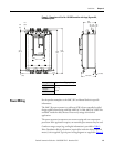
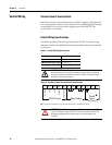
Control Wiring
Standard Control Terminal Block
SMC-50 controllers come standard with two 24V DC digital on/off inputs and
two relay outputs for auxiliary control functions. The standard digital I/O wiring
terminal block is located on the upper right portion of the SMC-50. The
terminal block is removable.
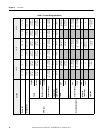
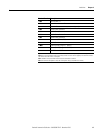
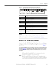
Control Wiring Specifications
The following table provides the specifications for all SMC-50 control wiring
and option module terminal blocks. Each wiring terminal will accept a maximum
of two wires.
Table 4 - Control Wiring Specifications
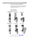
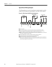
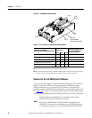
Figure 9 - Standard Control Terminal Block Identification
➊ See the controller nameplate to verify the control power ratings (120/240V AC or 24V DC).
Wire Size
0.2...2.5 mm
2
(#24...14 AWG)
Maximum Torque 0.8 N•m (7 lb•in.)
Maximum Wire Strip Length 7 mm (0.27 in.)
Screw Type M3 Slotted
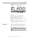
SHOCK HAZARD: To prevent the risk of electrical shock, disconnect all
power sources from the controller and option module before installing or
servicing it. Install the controller and option module in suitable enclosure
and keep it free of contaminants.
ATTENTION: IN1 DC (terminal 11) and IN2 DC (terminal 10) are 24V DC
inputs on controllers rated 120/240V AC and on controllers rated 24V DC.
Voltages exceeding specified input range may cause damage to the
controller.
Intl +24V DC
In1 DC
In2 DC
Enable I/O
Intl DC Common
24V DC Inputs
Aux 2
Aux 1
-L2
+L1
Relay Outputs
Control
Power
& Ground
12
11
10 9
8
7
65
4
32
1
➊