


Rockwell Automation Publication 150-QS003D-EN-P - November 2013 35
Programming Chapter 3
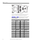
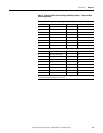
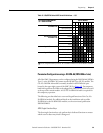
Table 11 - Rotary Switch Position Settings & Resulting Values — Ramp and Stop
Time Configurations
S3 = Ramp Time Configuration — Starting — Controller Parameter 50
Position Setting Starting Ramp Time [s] Position Setting Starting Ramp Time [s]
00.1 816
12 918
24 A20
36 B22
48 C24
5 10 (default) D 26
612 E28
714 F30
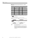
S4 = Stop Time Configuration — Controller Parameter 66
Position Setting
Stop Time [s]
➊
Position Setting
Stop Time [s] ➊
0 Coast -to-Stop (default) 8 16
12 918
24 A20
36 B22
48 C24
510 D26
612 E28
714 F30
➊ When the braking STOP MODE is selected (device configuration bank switch #3 and #4), the
controller multiplies the selected stop time by ten.