


Rockwell Automation Publication 150-QS003D-EN-P - November 2013 17
Installation Chapter 2
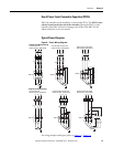
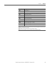
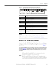
Terminal Number Description
1 ➌➍ Control Power +L1
2 ➌➍ Control Power Common -L2
3 Ground — To connect to the system/control ground point.
4 ➋➌ Auxiliary Relay Contact #1
5 ➋➌ Auxiliary Relay Contact #1
6 ➋➌ Auxiliary Relay Contact #2
7 ➋➌ Auxiliary Relay Contact #2
8 DC Internal I/O Power, DC Common
9 Enable I/O
10 ➊➌ Input #2 (24V DC) (range 15…30V DC)
11 ➊➌ Input #1 (24V DC) (range 15…30V DC)
12 +24V DC Internal I/O Power
➊
Do not connect any additional loads to this terminal. Parasitic loads may cause problems with operation.
➋ When set to external bypass mode, the auxiliary contact is used to control a properly sized external contactor
and overload once the motor is at full speed.
➌ RC snubbers are required when inductive loads are connected to terminal.
➍ See the controller nameplate to verify the control power ratings (120/240V AC or 24V DC)