


38 Rockwell Automation Publication 150-QS003D-EN-P - November 2013
Chapter 3 Programming
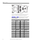
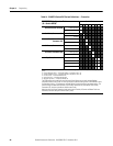
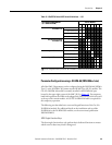
Table 14 - ON/OFF 8-Switch DIP Switch Definitions — Protection
PROTECTION Configuration Bank
(O = Switch OPEN)
Switch Number
#1 #2 #3 #4 #5 #6 #7 #8
Preset Protection Level
➊
Enable (default) 1
Disable 0
Stall Fault, Parameter 230 Enable (default) 1
Disable 0
Phase Reversal Fault,
Parameter 136
Enable 1
Disable (default) 0
OL Restart, Parameter 264 Enable 1
Disable (default) 0
OL Enable, Parameter 230 Enable (default) 1
Disable 0
Trip Class, Parameter 75 10 (default) 00
15 01
20 10
30 11
➊ The Preset Production Level DIP switch allows the following Faults to be enabled (1) or disabled (0) as a
group.
• Current Imbalance Fault — Parameter Number: 110 [default value: 15)
• Voltage Unbalance Fault — Parameter Number: 106 [default value: 15]
• Line Loss Fault — Parameter Number: NA
• Open Gate Fault — Parameter Number: NA
• No/Open Load Fault — Parameter Number: N
The PCM configuration setting for each of these Faults follows the currently entered/loaded
parameter value for each Fault. This will typically be the default setting unless a 20-HIM-A6 or other
configuration tool (e.g., PC software or network device) is used to change a parameter setting. The
switch setting also overrides the Motor Fault Enable, Parameter 230, and Starter Fault Enable,
Parameter 136, function to enable or disable these Faults.
Note that with the Preset Protection Level switch set to Disable, all Starter and Motor Faults are
disabled (as defaults except the Power Quality Fault).