


36 Rockwell Automation Publication 150-QS003D-EN-P - November 2013
Chapter 3 Programming
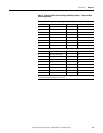
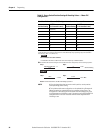
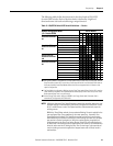
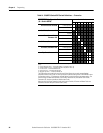
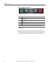
Table 12 - Rotary Switch Position Settings & Resulting Values — Motor FLC
Configurations
S5 = Motor Full Load Current (FLC) Configuration — Controller Parameter 78
Position Setting
FLC
➊➋
[% of controller’s max] Position Setting
FLC ➊➋
[% of controller’s max]
0 40 (default) 8 72
144 976
248 A80
352 B84
456 C88
560 D92
664 E96
768 F100
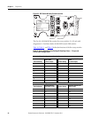
➊ Since a set of switches do not provide the resolution to enter all possible FLC combinations like a keypad,
switch S5 allows you to configure the motor’s FLC in the SMC-50 by using a percentage (%) of the controller’s
rated FLC (e.g., 90 A, 110 A, 180 A, etc.).
➋ To determine the S5 switch setting for an inside-the-delta motor configuration, use the following equations:
NOTE: 1 If the calculated value does not match a switch position, use the previous
(lower percentage) switch setting.
2 The inside-the-delta motor configuration can be selected using Parameter 44
(Motor Connection) or automatically during a controller tuning process. The
tuning process is done during the initial system start after changing any of the
tuning parameters and initializing a start or by pressing and holding the SMC-50
reset push button for at least 10 seconds with the motor stopped and then
initializing a start.
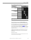
For a 60 A motor and a 90 A controller:
% of controller’s max FLC for a 60 A motor = 64% of 90 A (57.6 A), or Switch Position 6
EXAMPLE
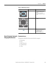
Step 1
Motor Nameplate FLC
1.73
= X
x 100 =
Step 2
X
SMC-50 Controller Rating
S5 Switch Setting
Step 1
100 A
1.73
= 57.8 A
Step 2
57.8 A
90 A
x 100 = 64%
EXAMPLE
Result From the result of 64%, the S5 switch setting is position 6.