


46 Rockwell Automation Publication 150-QS003D-EN-P - November 2013
Chapter 3 Programming
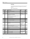
Quick Setup
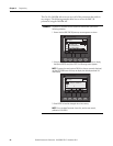
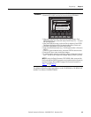
Access the basic programming configuration group in the Setup category. This
group provides a limited parameter set, allowing quick startup with minimal
adjustments.
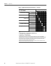
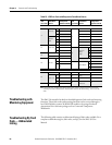
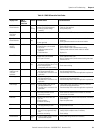
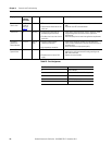
Table 19 - Quick Start Parameters
Parameter
Number
Parameter
Name Description/Function Value(s) Default
46 Line Voltage Enter the system 3-phase line voltage value. A value must be entered for the
voltage protection functions to work properly.
0…700V 480
47 Rated Torque Use for Torque Ramp Rating Starting Mode. Enter the maximum motor rated in
Newton meters.
1…1000 N•m 10
48 Rated Speed Use for Torque Ramp Rating Starting Mode. Enter the rated speed of the motor. 750, 900, 1500, 1800,
3500, 3600 RPM
1800
49 Starting Mode Enter the desired starting mode for the application.
Related Parameters for the Starting Mode:
Full Voltage: None
Current Limit: Current Limit Level, Ramp Time, Kickstart Time, Kickstart Level
Soft Start: Initial Torque, Ramp Time, Current Limit, Kickstart Time, Kickstart Level
Linear Speed: Initial Torque, Ramp Time, Current Limit
Torque Ramp: Starting Torque, Maximum Torque, Ramp Time, Current Limit,
Kickstart Time, Kickstart Level
Pump Start: Initial Torque, Ramp Time
Full Voltage, Current Limit, Soft
Start, Linear Speed, Torque
Ramp,
Pump Start
Soft Start
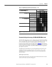
50 Ramp Time Enter the amount of time desired for the motor starting ramp to take. 0.0 - 1000 seconds 10
51 Initial Torque Motor torque level at which the start ramp begins. 0...90%LRT 70
52 Maximum
Torque
Use the Torque Ramp Starting mode. Enter the maximum motor torque at the end
of the start ramp required for the application.
0…300% 250
53 Current Limit
Level
Enter the value of the maximum current allowed during the ramp time. 50-600% FLC 350
56 Input 1 Allows the selection of how input 1 (CM terminal #11) effects the function of the
SMC-50 controller.
Disable, Start, Coast,
Stop Option, Start/Coast,
Start/Stop, Slow Speed,
Dual Ramp, OL Select,
Fault, Fault NC, Clear Fault,
Emergency Run,
Motor Heater
Start/Coast
57 Input 2 Allows the selection of how input 2 (CM terminal #10) effects the function of the
SMC-50 controller.
Disable
65 Stop Mode Enter the desired stopping mode for the application.
Related Parameters to the Stopping Mode:
Coast: None Soft Stop: Stop Time Linear Speed: Stop Time, Current Limit
Pump Stop: Stop Time SMB: Braking Current Ext. Brake: Stop Time
Coast, Soft Stop,
Linear Speed, Pump Stop,
SMB,
Ext. Brake
Coast
66 Stop Time Defines the time desired to ramp form run to stop for a specific stop mode. For Ext
Brake mode, the Stop Time = the time the Aux contact is closed to energize an
external brake.
0…999 seconds 0
75 Overload Class Enter the desired motor overload trip class. 5…30 10
77 Service Factor Enter the Service Factor of the
motor
. 0.01…1.99 1.15
78 Motor FLC Enter the motor specified Full Load Current (FLC) value. This value must be entered
to ensure the controller can provide proper motor current (e.g. - Overload)
protection.
1.0…2200.0 A 1.0
172 Aux1
Configuration
Allows selection of the operation for Auxiliary relay output contact #1 (control
module terminals #4 and #5).
➊
Normal, UTS, Fault, Alarm,
External Bypass, External
Brake, Auxiliary Control,
Network 1, Network 2,
Network 3, Network 4.
Normal
176 Aux 2
Configuration
Allows selection of the operation for Auxiliary relay output contact #1 (control
module terminals #6 and #7).
➊
Normal
➊ Normal = The contact is closed when the Start command is initiated and remains closed during a stop maneuver. After the stop is complete, the contact opens.