


Rockwell Automation Publication 150-QS003D-EN-P - November 2013 27
Installation Chapter 2
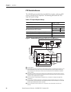
Bypass Diagrams
For bypass operation, a bypass contactor must be supplied. An auxiliary relay
contact that is programed for external bypass is used to control a properly sized
external contactor once the motor is at full speed.
Overload protection can be accomplished in several ways.
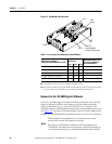
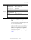
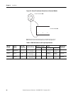
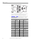
SMC-50 Providing Overload Function
• Frame B (90…180 A)
– Required parts: Cat. Nos. 150-SM2, 825-MCM180 converter module.
See Figure 19
.
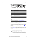
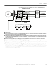
• Frame C and D (210…320 A and 361…520 A)
– Using bypass kit
• Required parts: Cat. No. 150-SCBK (Frame C) or 150-SDBK
(Frame D) See Tab le 9
and Figure 20.
Note: When using the Cat. No. 150-SCBK or 150-SDBK bypass
kit, the controller firmware must be FRN 3.001 or higher.
– Using 825 and CTs
• Required parts: Cat. Nos. 150-SM2, 825-MCM20, user supplied
CTs with 5 A secondary. See Figure 18
and Figure 19.
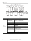
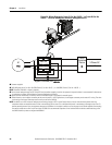
External Overload
• Frames B, C, and D
– Bypass contactor must be fully rated to motor Hp/kW and FLA. See
Figure 21
.
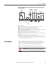
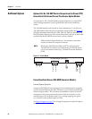
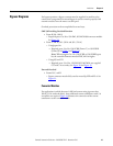
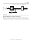
Converter Modules
For applications in which the motor’s full load current rating is greater than
180 A (311 A inside-the-delta), three additional current transformers with 5 A
secondaries are required. Figure 18
illustrates the connection of the current
transformers to the converter module.