


20 Rockwell Automation Publication 150-QS003D-EN-P - November 2013
Chapter 2 Installation
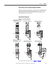
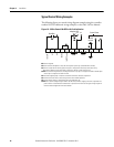
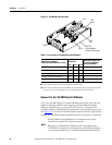
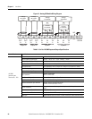
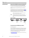
Figure 12 - Port Number Identification
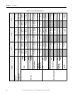
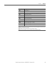
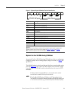
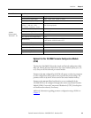
Table 5 - Port Location for Compatible Option Modules
❶ See the SMC-50 user manual for a list of compatible 20-COMM-X modules.
➋ When installed in an SMC-50 controller, 20-COMM-X modules physically reside in the space assigned to Port 9,
but connect to DPI Port 4 with the ribbon cable that is supplied with the communication module.
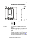
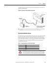
Optional Cat. No. 150-SM4 Digital I/O Module
A Cat. No. 150-SM4 Digital I/O Option Module provides four 120...240V AC
digital on/off inputs and three relay outputs to provide additional auxiliary
control or indications (e.g., up-to-speed (UTS), alarm, etc.) functions. The
150-SM4 module can be located in any of the three control module option ports
(See Figure 12
). Up to three 150-SM4 modules can be used with a single control
module. The 150-SM4 module terminal block used to wire the I/O is removable.
SMC-50 Control Module
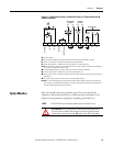
Compatible Option Modules Cat. Nos.
Compatible Control
Module Port
Maximum Number of this
Type of Option Module
per Control Module
Port 7 Port 8 Port 9
150-SM2: Ground Fault/PTC/External CT Yes Yes No 1
150-SM3: Analog I/O Yes Yes Yes 3
150-SM4: Digital I/O Yes Yes Yes 3
150-SM6: Parameter Configuration Yes Yes Yes 1
20-COMM-X ❶➋: Communications No No Yes 1
NOTE:
1 When installed in Control Module Port 7, the orientation of the module
terminal block is rotated 180° along with its terminals.
2 The Cat. No. 150-SM4 Digital I/O Module can NOT be configured using a
150-SM6 PCM. This module can be configured using a 20-HIM-A6, network card,
or communications software (e.g., Connected Components Workbench [CCW]).
Port 7
Port 9
HIM
Bezel
HIM
Port
SMC-50
Control Module
(shown without cover)
Port 8