


Rockwell Automation Publication 150-QS003D-EN-P - November 2013 21
Installation Chapter 2
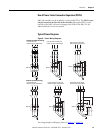
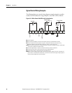
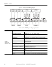
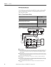
Figure 13 - Optional Digital I/O Module Terminal Identification
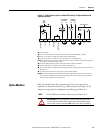
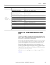
Optional Cat. No. 150-SM3 Analog I/O Module
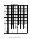
An optional Cat. No. 150-SM3 Analog I/O Module provides two analog inputs
(voltage or current) and two analog outputs (voltage or current), seeTab le 6
for
specifications.
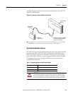
The 150-SM3 module can be located in any of the three control module option
ports (See Figure 12
). Up to three 150-SM3 modules can be used with a single
control module. The 150-SM3 module terminal block used to wire the I/O is
removable.
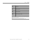
Terminal Number Description
A1 ➊ Optional Input #1 (120/240V AC)
A2 ➊ Optional Input #2 (120/240V AC)
A3 ➊ Optional Input #3 (120/240V AC)
A4 ➊ Optional Input #4 (120/240V AC)
A5 ➌ Input Common
A6 ➋➌ Optional Auxiliary Relay Contact #1
A7 ➋➌ Optional Auxiliary Relay Contact #1
A8 ➋➌ Optional Auxiliary Relay Contact #2
A9 ➋➌ Optional Auxiliary Relay Contact #2
A10 ➋➌ Optional Auxiliary Relay Contact #3
A11 ➋➌ Optional Auxiliary Relay Contact #3
A12 NO CONNECT
➊ Do not connect additional loads to this terminal. Parasitic loads may cause problems with
operation.
➋ When set to external bypass mode, the auxiliary contact is used to control a properly sized
external contactor once the motor is at full speed. See Figure 19
, Figure 20, and Figure 21.
➌ RC snubbers are required when inductive loads are connected to terminal.
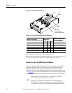
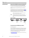
NOTE:
1 When installed in Control Module Port 7, the orientation of the module
terminal block is rotated 180° along with its terminals.
2 The Cat. No. 150-SM3 Analog I/O Module can NOT be configured using a
150-SM6 PCM. This module can be configured using a 20-HIM-A6, network card,
or communications software (e.g., Connected Components Workbench [CCW]).
InA1
InA2
InA3
InA4
InCOM
120V/240V AC Inputs
A1
A2 A3 A4 A5
Aux A1
Aux A2
Aux A3
NC
Relay Outputs
A10
A11
A12
A6
A7
A8
A9