191
LZT 123 7263 R1C
11. Input/Output
11.1 AT*E2IO Ericsson M2M Input/Output Read/Write
Description:
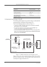
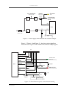
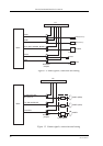
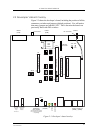
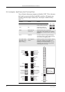
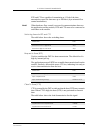
The module has 8 digital I/Os; 4 configurable GPIOs, 1 input-only, and
3 output-only.
The module also has 3 ADCs, and 1 DAC. All of these signals are
controlled by the AT*E2IO command.
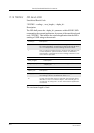
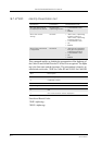
Note! IO1 to IO4 are set to INPUT as a factory default. Their status (Input/
Output) is stored in non-volatile memory.
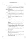
Set command controls the operations with the I/O signals for the M2M
devices. It is possible to perform up to 5 operations. These operations
have the following meaning:
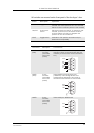
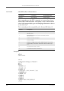
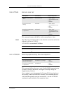
• Read (<op> = 0): It reads the state of the specified signal. It returns
the binary state of digital signals or value (0-255) of an ADC input
or the DAC output. In case of a digital I/O the command has the
following syntax:
AT*E2IO=0,“IO1”
*E2IO: 0,“IO1”,0
OK
If reading from the ADC/DACs:
AT*E2IO=0,“AD1”
*E2IO: 0,“AD1”,,62
OK
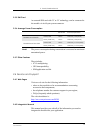
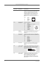
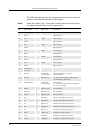
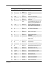
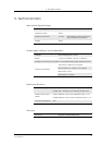
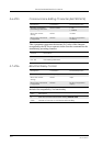
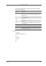
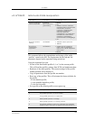
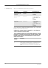
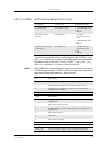
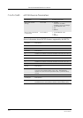
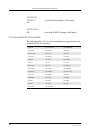
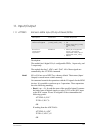
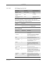
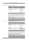
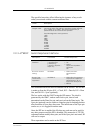
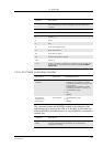
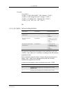
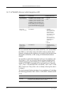
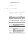
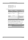
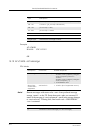
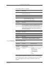
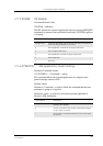
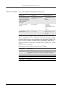
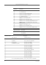
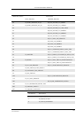
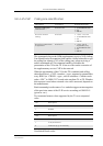
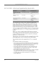
Description Command Possible Responses
Request operation
with the I/O signals
AT*E2IO=<op>,<io>
[,<val>][,<adc_val>]
•ERROR
•OK
• *E2IO: <op>,<io>[,[<val>]
[,<adc_val>]]
OK
Show if the
command is
supported
AT*E2IO=? • *E2IO: (list of supported
<op>s), <io>s,(list of
supported <val>s),(list of
supported <adc_val>s)
•ERROR