


2. SYSTEM CONNECTOR INTERFACE
47
LZT 123 7263 R1C
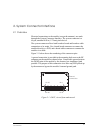
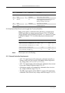
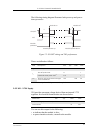
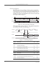
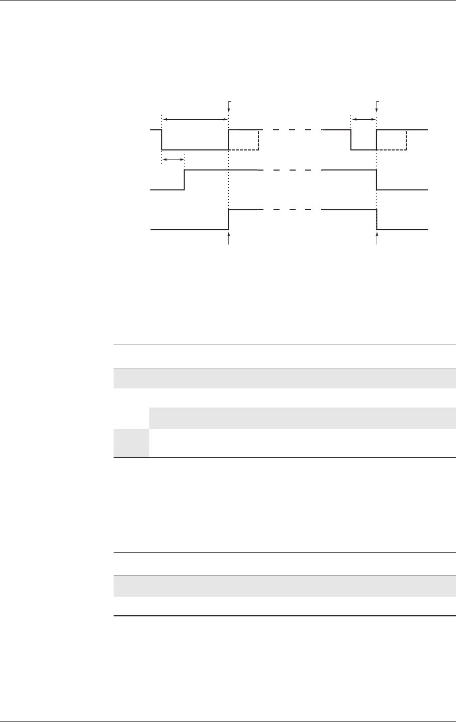
The following timing diagram illustrates both power-up and power-
down processes.
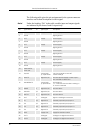
Figure 2.2 ON/OFF timing and VIO performance
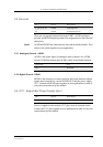
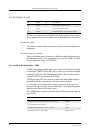
Times are defined as follows:
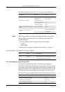
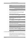
2.5.2 VIO - 2.75V Supply
VIO provides an output voltage derived from an internal 2.75V
regulator. Its electrical characteristics are shown below.
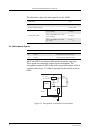
You can use this output for the following:
• to indicate that the module is alive;
• to power interface circuits, external to the module.
ON/OFF
VIO
Module
powered
t
1
t
2
t
pwr
Module power-up Module power-down
Module on Module off
Time Description Min. Typ. Max. Units
t
1
Turn-on pulse time ≥2 s
t
2
Turn-off pulse time ≥1 s
Hardware-reset pulse time
a
a. Active only when a full system reset is required.
>10 s
t
pwr
Time for VIO and internal voltages
to be established
100 200 ms
Parameter Min. Typ. Max. Units
Output Voltage (I
load
= 50mA) 2.70 2.75 2.85 V
Load current 75 mA