GM47/GM48 INTEGRATOR’S MANUAL
72
LZT 123 7263 R1C
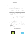
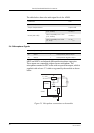
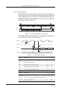
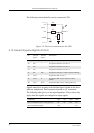
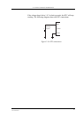
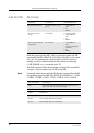
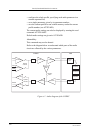
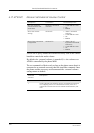
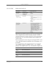
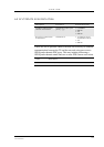
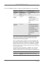
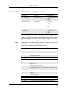
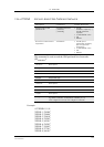
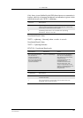
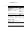
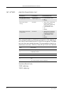
Grounds
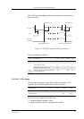
A ground connection is provided at the mounting hole next to the RF
connector on the module (see Figure 2.1, page 41). Connect this ground
point to the DGND pins of the module by the shortest, low-impedance
path possible. The purpose of this connection is to allow any ESD
picked up by the antenna to bypass the module’s internal ground path.
Note! It is recommended that you use a cable with a maximum resistance of
5mΩ for the ground connection.
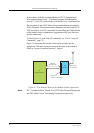
Note! AGND and DGND are connected at a star point inside the module. They
must not be joined together in your application.
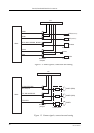
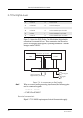
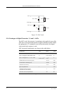
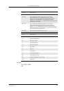
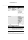
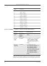
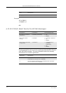
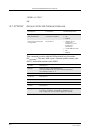
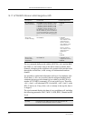
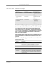
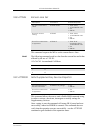
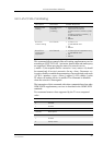
Audio
Use a coupling capacitor in ATMS line if the application does not use
the module’s bias voltage. See also “Figure 2.3 Microphone
connections to the module”, page 50.
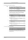
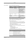
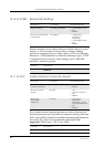
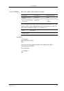
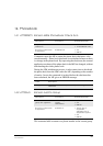
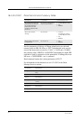
Software Upgrade
To upgrade the software, the system connector must be accessible in
your application. The pins SERVICE, TD, RD and the power signals
are used for this purpose. Please contact customer support for more
details.
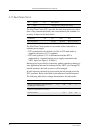
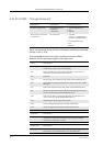
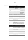
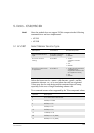
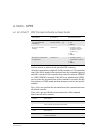
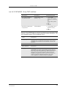
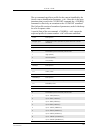
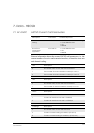
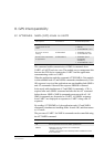
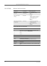
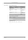
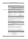
4.3 Antenna
4.3.1 General
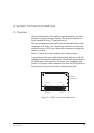
The antenna is the component in your system that maintains the radio
link between the network and the module. Since the antenna transmits
and receives electromagnetic energy, its efficient function will depend
on:
• the type of antenna (for example, circular or directional);
• the placement of the antenna;
• communication disturbances in the vicinity in which the antenna
operates.
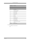
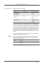
In the sections below, issues concerning antenna type, antenna
placement, antenna cable, and possible communication disturbances are
addressed.
In any event, you should contact your local antenna manufacturer for
additional information concerning antenna type, cables, connectors,
antenna placement, and the surrounding area. You should also