


2. SYSTEM CONNECTOR INTERFACE
55
LZT 123 7263 R1C
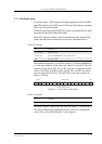
2.8 Serial Data Interfaces
The serial channels, consisting of three UARTs, are asynchronous
communication links to the application or accessory units. UART1 has
RS-232 functionality. UART2 and UART3 behave as general-purpose
serial data links. In addition they are used for accessories and GPS
respectively.
Digital 2.75V CMOS input/output electrical characteristics apply.
The standard character format consists of 1 start bit, 8 bit data, no parity
and 1 stop bit. In all, there are 10 bits per character.
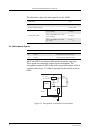
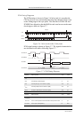
2.8.1 UART1 (RS232) - RD, TD, RTS, CTS, DTR, DCD and RI
UART1 signals conform to a 9-pin RS232 (V.24) serial port, except for
the DSR (CCITT N
o
107) signal. The DSR signal has been removed as
it is usually connected to DTR in most systems.
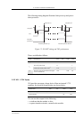
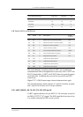
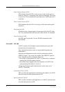
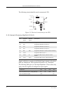
Typical Rise/Fall times Rise Time Fall Time Unit
PCMCLK 19 18 ns
PCMSYN 19 15 ns
PCMOUT 900 900 ns
PCMDLD 20 19 ns
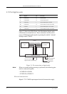
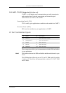
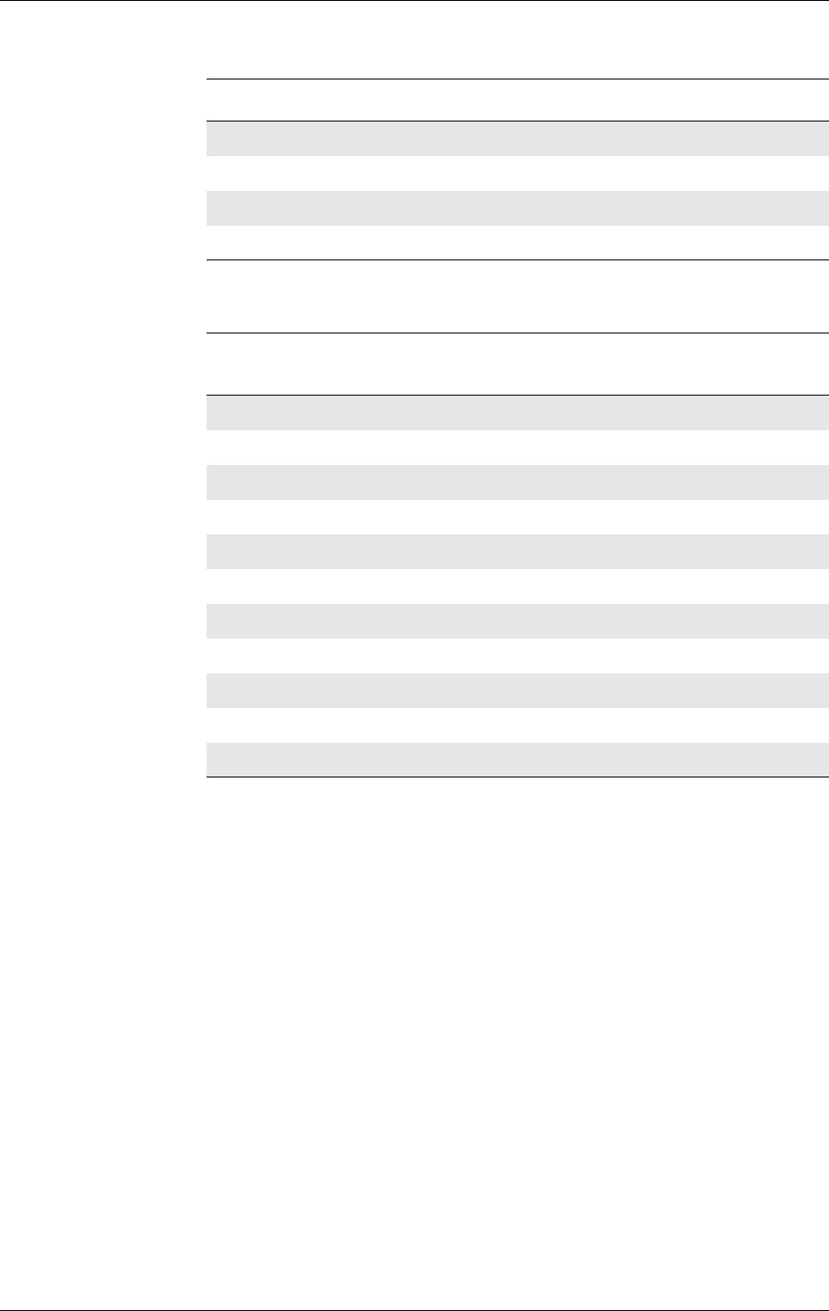
Pin Signal Dir Description RS232
CCITT Nº
41 TD I Serial data to module (UART1) 103
42 RD O Serial data from module (UART1) 104
39 RTS I Request To Send (UART1) 105
40 CTS O Clear To Send (UART1) 106
37 DTR I Data Terminal Ready (UART1) 108.2
38 DCD O Data Carrier Detect (UART1) 109
36 RI O Ring Indicator (UART1) 125
45 TD2 I UART2 Data Transmission
46 RD2 O UART2 Data Reception
43 TD3 I UART3 Data Transmission
44 RD3 O UART3 Data Reception