


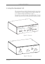


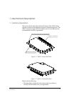
2. USING THE DEVELOPER’S KIT
33
LZT 123 7263 R1C
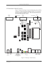
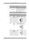
All switches are mounted on the front panel of the developer’s box.
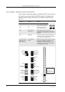
Switch Description Operation
Vcc Toggle switch Switches power from external power supply to
module. Has three positions; NC, OFF and ON.
Switch to ON to connect power to the module
ON/OFF Push button
switch
Switches module on and off. To power up the
module, push button for at least 2 seconds,
until the yellow VIO LED is on. Repeat the
process to turn the module off
DCIO Toggle switch Maintain in OFF position. Included only for
backwards compatibility
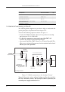
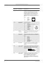
Connector Description Connections
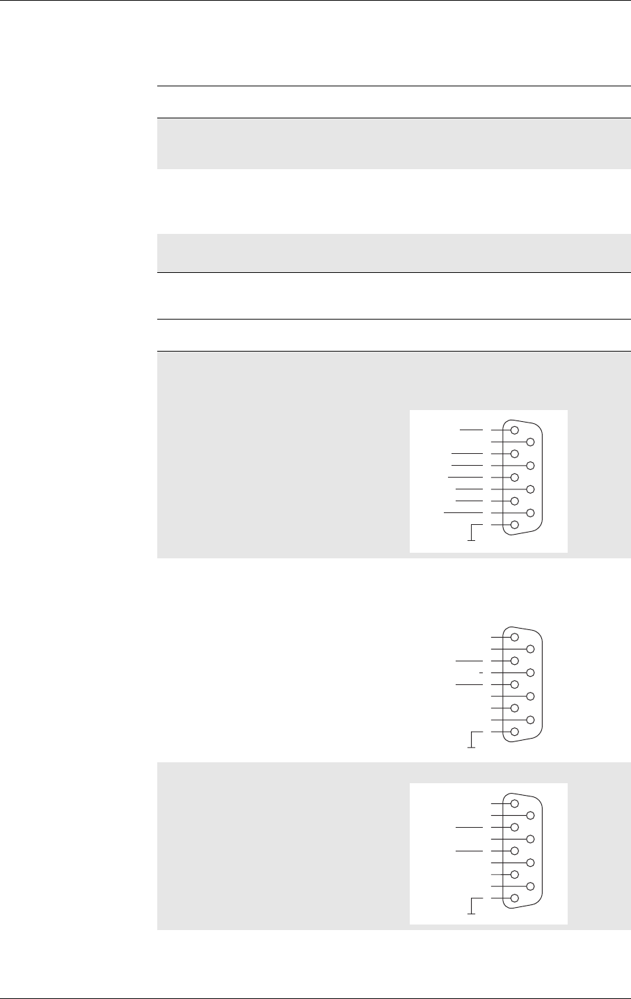
UART1
(EDB)
9-way
Dsocket
(accessible
on the rear
panel)
Full 9-pin RS232 communication port. Used
during run-time to communicate with the
module (AT-commands, data transmission,
etc.)
UART2
(ACB)
9-way
Dsocket
(accessible
on the rear
panel)
3 line RS232 communications port
(+SERVICE). Used during service and
maintenance operations. Also used to
download new software to the module
UART3 9-way
Dsocket
(accessible
on the rear
panel)
3 line serial port. RS232 levels
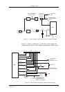
DCD
RD
RTS
TD
CTS
DTR
1
2
7
3
8
4
6
5
9RI
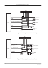
RD2
TD2
1
2
7
3
8
4
6
5
9
SERVICE
RD3
TD3
1
2
7
3
8
4
6
5
9