11. INPUT/OUTPUT
193
LZT 123 7263 R1C
*E2IO: 3,“I5”,1 (I5 triggered, current state ‘1’)
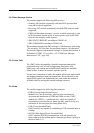
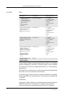
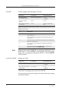
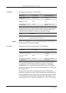
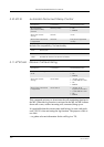
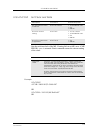
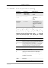
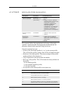
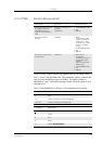
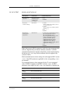
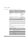
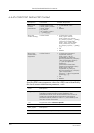
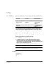
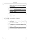
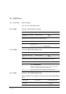
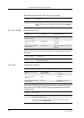
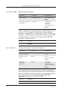
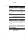
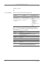
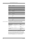
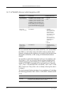
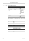
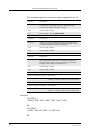
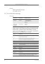
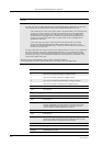
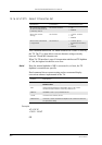
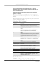
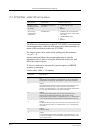
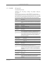
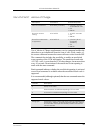
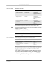
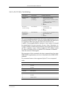
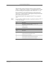
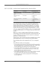
• Trigger Check (<op> = 5): Checks if a signal input is configured as
a trigger. Returned <val> shows the current trigger state; ‘1’ for
triggered or ‘0’ for not triggered. If the signal is triggerable, the
current trigger status and OK are return, otherwise ERROR is
returned.
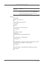
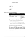
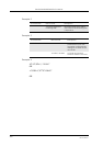
AT*E2IO=5,“I5”
*E2IO: 5,“I5”,1 (I5 is currently set to trigger)
OK
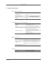
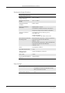
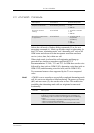
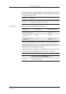
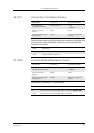
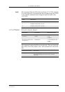
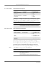
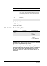
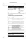
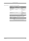
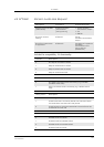
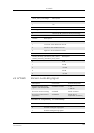
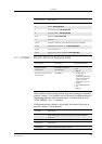
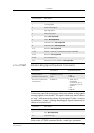
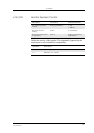
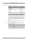
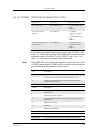
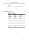
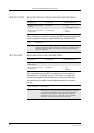
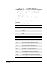
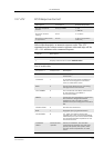
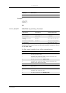
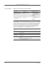
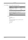
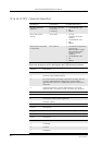
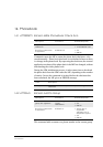
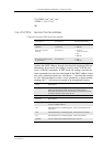
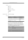
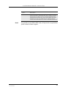
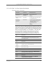
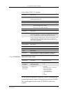
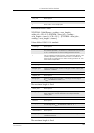
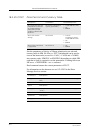
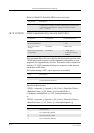
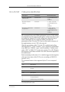
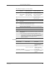
The test command returns the supported I/Os and allowed value ranges.
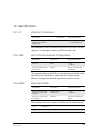
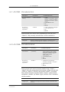
Abortability:
This command may not be aborted.
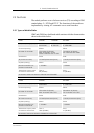
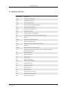
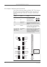
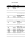
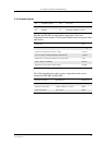
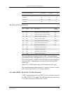
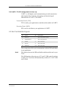
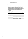
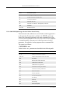
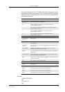
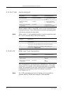
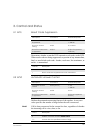
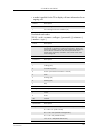
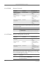
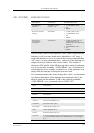
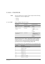
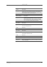
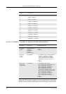
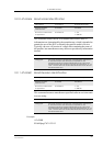
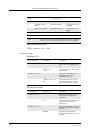
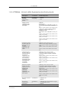
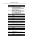
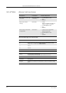
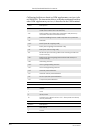
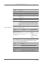
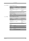
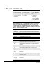
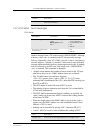
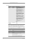
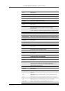
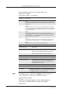
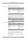
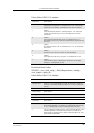
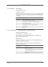
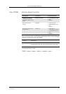
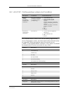
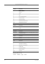
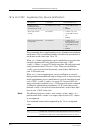
<op> Description
0 Read
1 Write
2 Configure
3 Configure Check
4 Trigger
5 Trigger Check
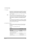
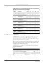
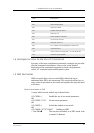
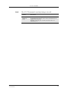
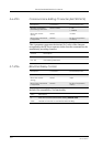
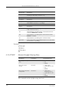
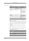
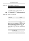
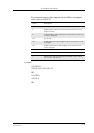
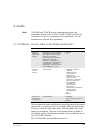
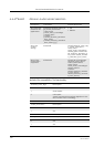
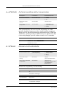
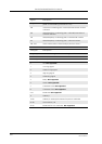
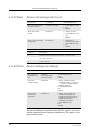
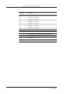
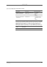
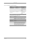
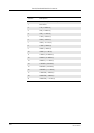
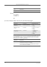
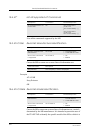
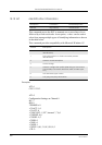
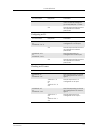
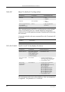
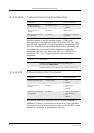
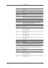
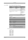
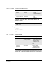
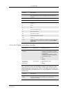
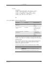
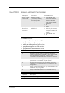
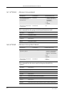
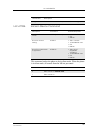
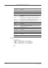
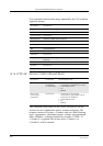
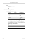
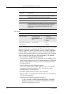
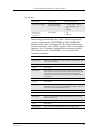
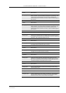
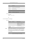
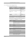
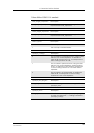
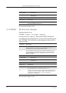
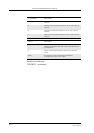
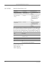
<io> Description
“IO1” Digital Input 1. Supported Operations: 0,1,2,3,4,5
“IO2” Digital Input 2. Supported Operations: 0,1,2,3,4,5
“IO3” Digital Input 3. Supported Operations: 0,1,2,3,4,5
“IO4” Digital Input 4. Supported Operations: 0,1,2,3,4,5
“I5” Digital Input 5. Supported Operations: 0,4,5
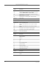
“O5” Digital Output 5. Supported Operations: 0,1
“O6” Digital Output 6. Supported Operations: 0,1
“O7” Digital Output 7. Supported Operations: 0,1
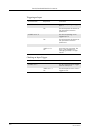
“DA1” Digital/Analogue Input: Supported Operations: 0,1
“AD1” Analogue/Digital Output 1: Supported Operations: 0
“AD2” Analogue/Digital Output 2: Supported Operations: 0
“AD3” Analogue/Digital Output 3: Supported Operations: 0