


2. SYSTEM CONNECTOR INTERFACE
61
LZT 123 7263 R1C
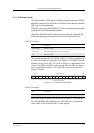
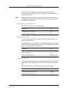
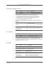
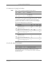
2.10 Service/Programming
When the SERVICE input signal is active the module will:
• be reprogrammed if data is received through UART2 from a
computer running Sony Ericsson reprogramming software;
• or it will output logging data on UART2.
The electrical characteristics are given below. The signal reference is
DGND.
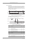
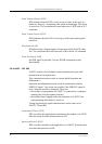
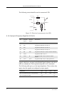
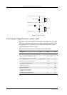
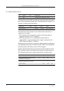
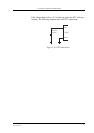
2.11 Buzzer
Connecting the BUZZER signal to an inverting transistor-buffer
followed by a piezoelectric transducer enables the module to play pre-
programmed melodies or sounds.
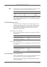
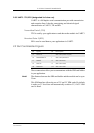
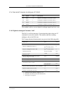
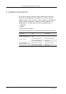
2.12 LED
The LED states shown below, are hard coded.
Pin Signal Dir Description
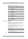
58 SERVICE I Flash programming voltage
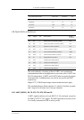
Mode
SERVICE Voltage (V)
Drive Capacity
Min. Typ. Max.
Normal Operation 0.8 -
Service/enable
programming
1.9 2.75 13.6 >1mA
Pin Signal Dir Description
31 BUZZER O Buzzer output from module
Pin Signal Dir Description
33 LED O LED Output from module
LED indication Operational status
No indication No power or in the OFF state
Green, steady Power on, not connected to a network
Green, blinking Power on, connected to a network