


GM47/GM48 INTEGRATOR’S MANUAL
42
LZT 123 7263 R1C
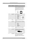
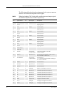
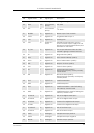
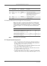
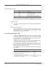
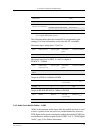
The following table gives the pin assignments for the system connector
interface and a short description for each signal.
Note! Under the heading “Dir” in the table, module input and output signals
are indicated by the letters I and O respectively.
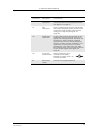
Pin Signal Name Dir Signal Type Description
1 VCC - Supply Power supply
2 DGND - - Digital ground
3 VCC - Supply Power supply
4 DGND - - Digital ground
5 VCC - Supply Power supply
6 DGND - - Digital ground
7 VCC - Supply Power supply
8 DGND - - Digital ground
9 VCC - Supply Power supply
10 DGND - - Digital ground
11 VCC - Supply Power supply
12 DGND - - Digital ground
13 Reserved for
future use
14 ON/OFF I Internal pull
up, open drain
Turns the module on and off.
Former WAKE_B
15 SIMVCC - Digital 3V/5V SIM card power supply. Power output
from module for SIM Card
16 SIMPRESENCE I Internal pull
up, open drain
SIM Presence
A “1” indicates that the SIM is missing; a
“0” that it is inserted
17 SIMRST O Digital 3V/5V SIM card reset
18 SIMDATA I/O Digital 3V/5V SIM card data
19 SIMCLK O Digital 3V/5V SIM card clock
20 DAC O Analogue Digital to analogue converter
21 IO1 I/O Digital 2.75 General purpose input/output 1
22 IO2 I/O Digital 2.75 General purpose input/output 2
23 IO3 I/O Digital 2.75 General purpose input/output 3
24 IO4 I/O Digital 2.75 General purpose input/output 4
25 VRTC I Supply 1.8V Supply for real time clock
26 ADC1 I Analogue Analogue to digital converter 1
27 ADC2 I Analogue Analogue to digital converter 2