


2. SYSTEM CONNECTOR INTERFACE
63
LZT 123 7263 R1C
2.14 General Purpose Analogue I/O Ports
The module is able to convert digital to analogue signals and vice versa.
2.14.1 Digital to Analogue Converter - DAC
The DAC is an 8-bit converter. Conversion takes place when an AT
command is sent to the module. The module sends the resulting
analogue value to the DAC pin.
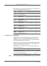
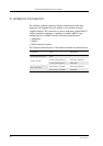
DAC output electrical characteristics are given in the following table.
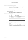
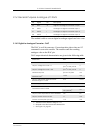
Pin Signal Dir Description
20 DAC O Digital to analogue conversion output
26 ADC1 I Analogue to digital conversion input 1
27 ADC2 I Analogue to digital conversion input 2
28 ADC3 I Analogue to digital conversion input 3
Parameter Limit Units
Resolution 8 Bits
Output voltage for code = 0
(2.75
a
x 0.05) ± 0.05
a. Tolerance on this internal voltage is ±5%
V
Output voltage for code = 255
(2.75
a
x 0.95) ± 0.05
V
Nominal step size
(2.75
a
x 0.9)/256
mV
Absolute error
b
b. Referred to the ideal conversion characteristic.
≤ ± 0.5 mV
Output wide-band noise and clock
feed-through 0-1.1MHz
≤0.5 mV
rms
Power-supply rejection ratio 50Hz - 10kHz ≥40 dB
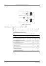
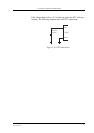
Conversion rate ± 0.5LSB
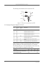
≤2 (Load A)
c
c. See Figure 2.9, page 64
ms
≤50 (Load B)
c
ms
Output buffer impedance when disabled ≥50 kΩ
Output current source or sink ≥1 mA
Current consumption (active) ≤1.0 mA