


GM47/GM48 INTEGRATOR’S MANUAL
64
LZT 123 7263 R1C
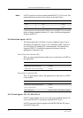
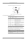
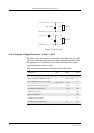
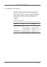
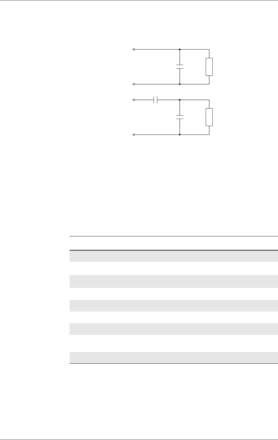
Figure 2.9 DAC loads
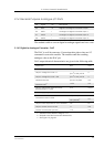
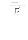
2.14.2 Analogue to Digital Converters 1, 2 and 3 - ADCx
The ADC is an 8-bit converter. An analogue value applied to any of the
ADC pins is converted and stored in a register inside the module. When
the appropriate AT command is received by the module, the digital
value stored in the register is read.
ADC electrical characteristics are shown in the table below.
1k
DGND
DAC
1nF
10nF
Load B
100k
DGND
DAC
100 - 200pF
Load A
Parameter Min. Max. Units
Resolution 8 8 Bits
Input voltage for 0000 0000 word 0
0.01 x 2.75
a
a. Tolerance on this internal voltage is ±5%
V
Input voltage for 1111 1111 word
0.99 x 2.75
a
2.75
a
V
Differential Non-Linearity (DNL) ±0.75 LSB
Overall Non-Linearity (INL) ±0.60 LSB
Absolute accuracy ±1.5 LSB
Input impedance 1 MΩ
Average supply current
(continuous conversion)
1 mA
External source impedance 50 kΩ