


1. OPERATIONAL OVERVIEW
1-6
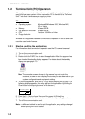
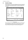
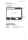
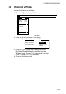
1.3 Standby Display
After the equipment is turned on and the diagnostic test has been conducted, the
standby display appears, showing the system status monitor. The system status
monitor provides various operating information. For a detailed description, see
paragraph 7.4.
File Edit Transmit EGC Reports Logs Options Setup Position StopAlarm
Date
Time
Position
Waypoint
Course 345 DEG
Speed 10.2 KTS
Current NCS
Current Channel
Current TDM
MES Status
GPS Status
DCE Memory
02-02-25
01:32 (UTC)
LAT 34:30.00N
LON 135:00.00E
LAT
LON
344 (IOR) LOGOUT
NCS CC
NCS CC
Idle
2D
32818 Bytes free
IMN:
BBER
C/N
Send Level
Rx AGC Level
REF Offset Freq
Synthe Local
VCXO Control 131
Antenna Power Supply
Water Temperature
Water Current
Direction
Speed
Depth
443156710
000
OK ( 0dB)
OK ( 0)
OK (135)
OK ( 0Hz)
OK
OK
Current State: IDLE
DCE F16 Ver. ##
UNSYNC
NCS: IOR LOGOUT LAT: 34:30.00N
LON: 135:00.00E
02-02-25 01:32 (UTC)
DEG
DEG
KTS
## = Version No. of RF CON Board
Standby display
After the diagnostic test has been completed, the equipment automatically starts
synchronizing itself with a satellite. When the indication “Retuning” is replaced
with “ SYNC(NCS), the synchronization process is completed. Then, you are
ready to receiving EGC messages. For further details see paragraph 2.4.