94
Appendix
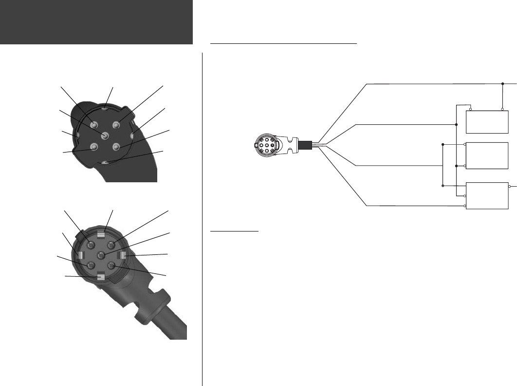
Wiring and Interfacing
Unit Power/Data Connector
Data Out 1
Blue
Ground
Black
Voice (-)
Orange
Data In 2
Green
Alarm
White
Power
Red
Voice (+)
Brown
Data In 1
Yellow
Data Out 2
Violet
Power/Data Cable Connector
Data Out 1
Blue
Ground
Black
Voice (-)
Orange
Data In 2
Green
Alarm
White
Power
Red
Voice (+)
Brown
Data In 1
Yellow
Data Out 2
Violet
Connecting the Power/Data Cable
The power/data cable connects the GPSMAP 276C to an 11–35-Volt DC system and provides interface
capabilities for connecting external devices. The color code in the diagram below indicates the appropri-
ate harness connections. Replacement fuse is a 3AG - 1.5 Amp fuse.
Blue: Data Out 1
Yellow: Data In 1
Black: Ground
Red: Power
11–35V DC
(-)(+)
Autopilot/
NMEA Device
RXD +
RXD -
GBR 23
Beacon
Receiver
(-)
(+)
Brown
Blue
Interfacing
The following formats are supported for connection of external devices: GARMIN proprietary Dif-
ferential GPS (DGPS), NMEA 0180, 0182, 0183 (versions 1.5, 2.0, 2.3, 3.01), ASCII Text Output, and
RTCM SC-104 input (version 2.0).
The following are the Approved Sentences for NMEA 0183, version 3.01 output: GPRMC, GPGGA,
GPGSA, GPGSV, GPGLL, GPBOD, GPRTE, and GPWPL. The following are the Proprietary Sentences for
NMEA 0183, version 3.01 output: PGRME, PGRMZ, and PSLIB.
The GPSMAP 276C also includes NMEA input with support for the BWC, DBT, DPT, MTW, VHW,
and XTE sentences.
Garmin’s proprietary communication protocol is available from the Web site (www.garmin.com).
190-00335-00_0A.indd 94 4/7/2004, 1:51:17 PM


