


11. MAINTENANCE & TROUBLESHOOTING
11-3
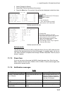
11.2 Maintenance
Regular maintenance helps to keep your equipment in good condition and prevents
future problems. Check the items shown in the table below.
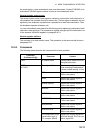
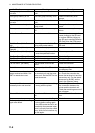
Item Check point Remedy/Remarks
Antenna Check for physical damage and corro-
sion.
Replace damaged parts.
Wire antenna Check that the antenna is properly
spanned and separated sufficiently
from metallic structures.
If necessary, re-span antenna.
Insulators for
antenna
Check for salt water deposits on insula-
tors. Check that connection at the lead-
in insulator is tight and rust-free.
Replace damaged insulator(s). Re-
move salt water deposits. Clean with
fresh water, then dry. Remove rust,
then tighten bolts and lock nuts. Cover
metallic surface with sealing compound.
Antenna cou-
pler
• Check condition of antenna terminal,
ground, coaxial cable and control ca-
ble.
• Check that coupler lid and cable
glands are firmly secured.
• Check for physical damage, corro-
sion and salt water deposits.
• Tighten the loosened connections.
• Fasten the lid firmly and evenly to
prevent water leakage.
• Replace if damaged.
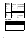
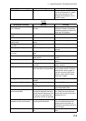
Control unit • Check ground connection, control ca-
ble, and external equipment.
• Confirm that there are no objects on
the top of the control unit.
• Remove dust from control unit with
soft cloth.
Note: Do not use chemical cleaners to
clean the control unit; they can remove
paint or markings and deform the equip-
ment.
• Tighten the loosened connections;
remove foreign materials from con-
nectors.
• Remove any objects.
• Wipe the LCD carefully to prevent
scratching, using tissue paper and an
LCD cleaner. To remove dirt or salt
deposits, use an LCD cleaner, wiping
slowly with tissue paper so as to dis-
solve the dirt or salt. Change paper
frequently so the salt or dirt does not
scratch the LCD.
Transceiver
unit
• Check connection at signal cable, co-
axial cable, control cable, power ca-
ble, and navigator.
• Confirm that there are no objects on
the top of the cabinet.
• Tighten loosened connections; re-
move foreign materials from connec-
tors.
• Remove any objects.
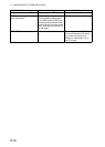
Power supply Check that the supply voltage at trans-
mission is within the rated range (21.6
to 31.2 VDC at the power connector).
If not within the range, check power
source. Low voltage may cause erratic
operation.