


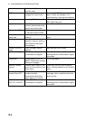

12 MAINTENANCE & TROUBLESHOOTING
12-2
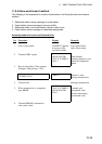
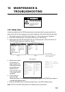
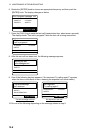
12.2 Radiotelephone Test
Do the following to check the radiotelephone for proper operation:
1. At the radiotelephone screen, press the [3/TEST] key to start the test. OK or NG (No
Good) appears as the test result for each item checked. For NG, contact your dealer
for advice.
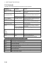
Tx selfcheck
PLL : OK PA2 : OK*
COMB : OK*
RF : OK TX FIL : OK
PA1 : OK COUPL : OK
* FS-2570 only
2. Press the [CANCEL] key to quit the test and return to the previously used screen.
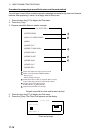
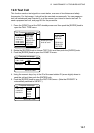
12.3 Antenna Coupler Test
The CPU and the relays which choose capacitors and coils for tuning can be checked. For
qualified technicians only.
DANGER
HIGH TENSION HAZARD
Circuits in the antenna
coupler are still alive at OFF.
Discharge before servicing.
1. Open the antenna coupler cover.
2. Open the shield cover inside the coupler.
3. Turn on the #2 switch of DIP switch S2.
4. Press the TUNE switch in the antenna coupler.
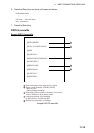
5. 24 LEDs (CR1 to CR24) light one by one every second. Relays trip on with
corresponding LEDs as below.
CR1 ON – K1 ON
CR2 ON – K2 ON
.
.
.
CR22 ON – K22 ON (CR23 not provided)
CR24 ON – K24, K25 ON
6. Turn off the #2 switch of DIP switch S2.
7. Close the cover.
If CPU error is detected, CR1 lights for ROM error, CR2 for RAM error, CR3 for A/D
converter error. (ROM/RAM/ A/D converter is incorporated in the CPU.)
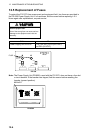
COUPLER BOARD
LED
DIP switch S2
behind the shield case
TUNE SWITCH