


OnCell G2150I AT Command Set V24-V25 Commands
9-4
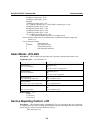
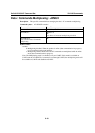
AT+IFC=0,0 OK
Note: New values
Defined values:
< DCE_by_DTE >
0: none (supported)
1: XOn/Xoff local circuit 103 ( not supported)
2: RTS (supported)
3: Xon/Xoff global on circuit 103 (not supported)
Important note: When this parameter is set to 2 (DTE invokes flow control through RTS) DCE
behavior is as follows:
If the DCE has never detected RTS in the high (or ON) condition since startup, then it ignores
RTS (assuming this signal is not connected).
As soon as the DCE detects RTS high the signal acts on it. Therefore subsequent RTS
transition to OFF will prevent the DCE from sending any further data in both online and offline
modes.
This behavior allows the user to use the default settings (hardware flow control) and leave RTS
disconnected. In the case where RTS is connected and is high at least once, it acts on the DCE.
< DTE_by_DCE >
0: none (supported)
1: Xon/Xoff circuit 104 (not supported)
2: CTS (supported)
When this parameter is set to 0 (none) then CTS is kept high all the time.
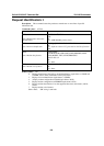
Set DCD Signal: &C
Description: This command controls the Data Carrier Detect (DCD) signal.
G2150O products differ slightly from V25ter Recommendation. DCD signal (“Circuit
1rned ON at the same time the CONNECT message is sent, whereas the specification states the
DCD should be turned ON after the CONNECT message was received.
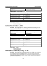
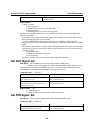
Command syntax: AT&C<n>
Command Possible responses
AT&C0
Note: DCD always on
OK
Note: Command valid
AT&C1
Note: DCD matches state of the remote
modem’s data carrier
OK
Note: Command valid
Defined values: <n>
0 DCD always on
1 DCD matches state of the remote modem’s data carrier
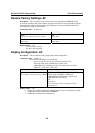
Set DTR Signal: &D
Description: This command controls the Data Terminal Ready (DTR) signal
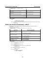
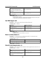
Command syntax: AT&D<n>
Command Possible responses
AT&D0
Note: The DTR signal is ignored
OK
Note: Command valid