


36 Chapter 2
Operating Overview
Displaying Analog Measurements
Displaying Analog Measurements
RF Measurements
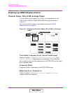
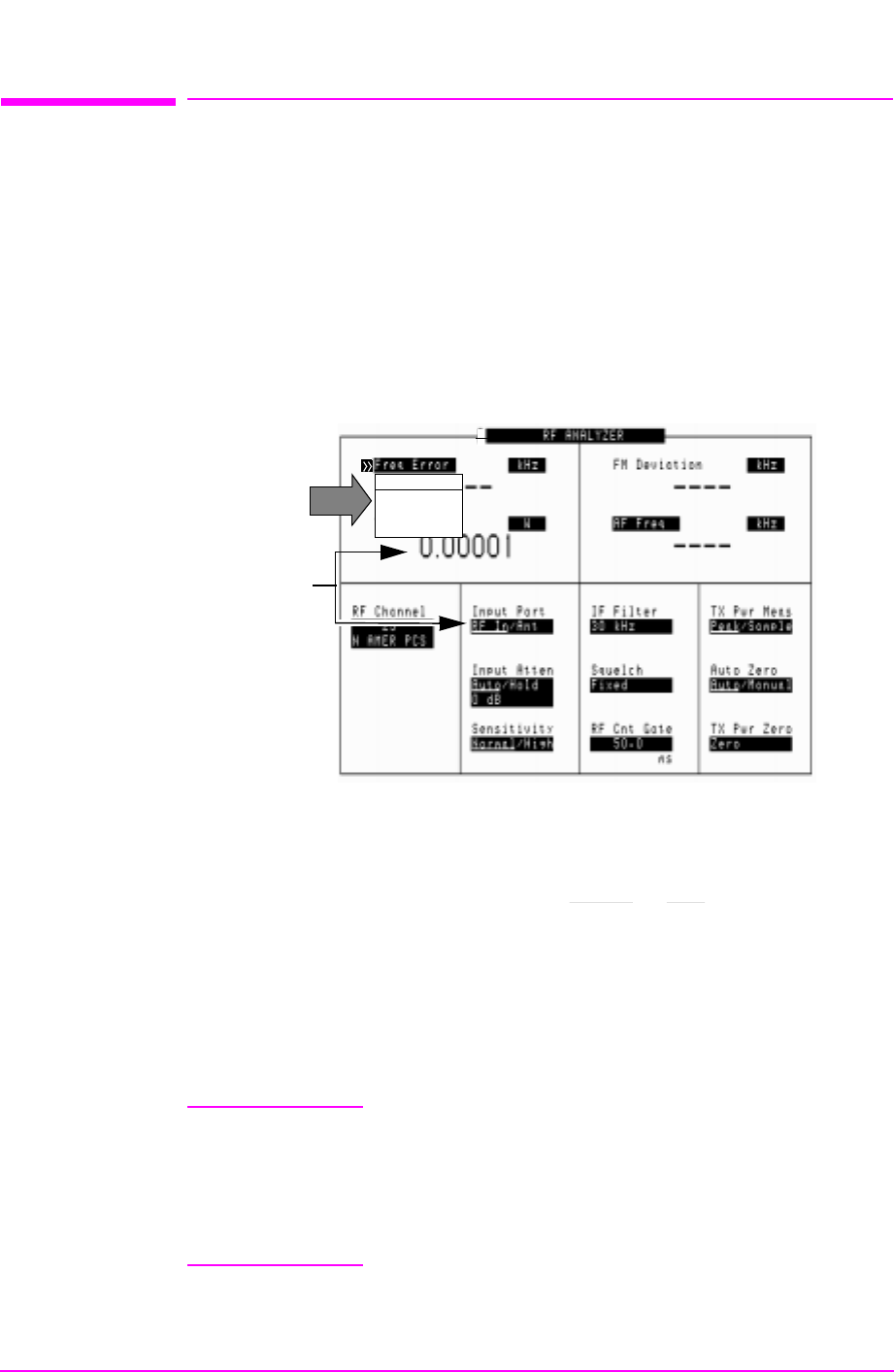
Frequency Error, Frequency
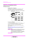
RF Frequency Error and RF Frequency are displayed on the RF
ANALYZER, RF GENERATOR, and AF ANALYZER screens.
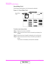
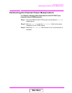
Figure 2-3 Displaying RF Frequency Error or RF Frequency,
and TX Power
Transmitter (TX)Power
TX Power is only measured and displayed here when the Input Port
on the RF ANALYZER screen is set to RF In. If Ant (antenna) is
selected, the measurement is replaced by four dashes (- - - -).
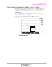
You can measure low power levels on the ANT IN port using the
spectrum analyzer.
Refer to the "TX Power Measurement" field on page 120 and the "TX
Pwr Zero" field on page 157 for more information on measuring
transmitter power.
CAUTION Connecting a signal of >60 mW to the ANT IN (antenna)
port can cause instrument damage (although internal
protection circuits can typically withstand a
short-duration signal of 1 or 2 Watts). If the overpower
circuit is triggered, remove the signal from the ANT IN
port and turn the Test Set off and on to reset it.
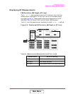
Choices:
Freq Error
Frequency
TX
Power
Main Menu