


72 Chapter 3
Overview of the Test Set’s Built-In Tools
Using the Oscilloscope (Scope)
Selecting the Oscilloscope’s Input
Step 1. Press Shift, then RF Anl (AF Anl) to select the AF ANALYZER
screen.
Step 2. Select the AF Anl In field. A list of choices appears.
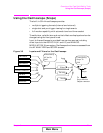
Step 3. Select the desired input to the scope:
• FM Demod for FM demodulated audio from input signals connected
to the RF IN/OUT or ANT IN connectors.
• AM Demod for AM demodulated audio from input signals connected
to the RF IN/OUT or ANT IN connectors.
• SSB Demod for SSB demodulated audio from input signals
connected to the RF IN/OUT or ANT IN connectors.
• Audio In for a signal connected to the AUDIO IN connector.
• Ext Mod for a signal connected to the ANALOG MODULATION IN
connector.
• FM Mod for the FM modulated audio from the RF generator section.
• AM Mod for the AM modulated audio from the RF generator section.
• Audio Out for the signal present at the SCOPE MONITOR
OUTPUT connector.
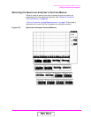
The input to the oscilloscope is displayed on the SCOPE screen.
Selecting the Oscilloscope’s Filters
Step 1. Press Shift, then RF Anl (AF Anl) to select the AF ANALYZER
screen.
Step 2. Select the Scope To field. A list of choices should appear.
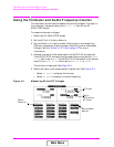
Step 3. Select the desired filtering for the signal:
• Input if you want no filtering (dc coupled)
• Filters to route the audio to the oscilloscope after passing through
Filters 1 and 2 (ac coupled).
• De-emp to route the audio to the oscilloscope after passing through
Filters 1 and 2, and the de-emphasis circuitry (ac coupled).
• Notch to route the audio to the oscilloscope after passing through
Filters #1 and #2, the de-emphasis circuitry, and notch circuitry (ac
coupled).
Main Menu