


60 Chapter 3
Overview of the Test Set’s Built-In Tools
Using RF Tools Program
Swept Return Loss
This test radiates a test signal when testing antennas or cables with
antennas attached to them. Verify that the level and frequency span
used for the test cannot result in interference to other nearby antennas.
To minimize interference when running the program, set the power
level at the DUPLEX OUT port to the minimum value needed for good
measurement resolution. Set the frequency range carefully.
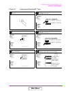
This test measures the return loss of a cable or device in the swept
mode. A SWR bridge and two 6 dB pads are connected to the Test Set.
The pads are used to reduce impedance mismatch errors between the
SWR bridge and the DUPLEX OUT and ANT IN ports on the Test Set.
You will be prompted at the start of the test to enter the start and stop
frequencies. A reference level is measured first with a short or open on
the DUT port of the SWR bridge. Then the return loss is measured with
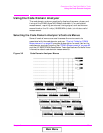
the cable or antenna-under-test. The trace showing return loss over the
frequency band selected is displayed on the screen. Measured values for
best and worst case return loss are printed at the top of the screen.
VSWR can be calculated from the return loss.
The following formula can be used to determine the VSWR from the
return loss:
VSWR
VSWR is sometimes stated as a ratio. For example: 1.2:1 or “one point
two to one” VSWR. The first number in the ratio is calculated from the
formula above. The second number in the ratio is always one. Table 3-1
and Table 3-2 contain some of the values from this calculation.
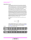
Table 3-1 Return Loss (0 to 20 dB) to VSWR
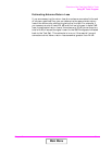
Table 3-2 Return Loss (20 to 40 dB) to VSWR
VSWR
110
RL–
20
------- ---
+
110
RL–
20
----- -----
–
-----------------------=
Return Loss (dB)0 2 4 6 8 101214161820
VSWR 8.7 4.4 3.0 2.3 1.92 1.67 1.50 1.38 1.29 1.22
Return Loss (dB) 20 22 24 26 28 30 32 34 36 38 40
VSWR 1.22 1.17 1.13 1.11 1.08 1.07 1.05 1.04 1.03 1.03 1.02
∞
Main Menu