


INSTALLATION-DK 16 KSU & PCB
SECTION 100-816-205
MARCH 1993
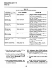
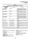
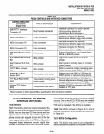
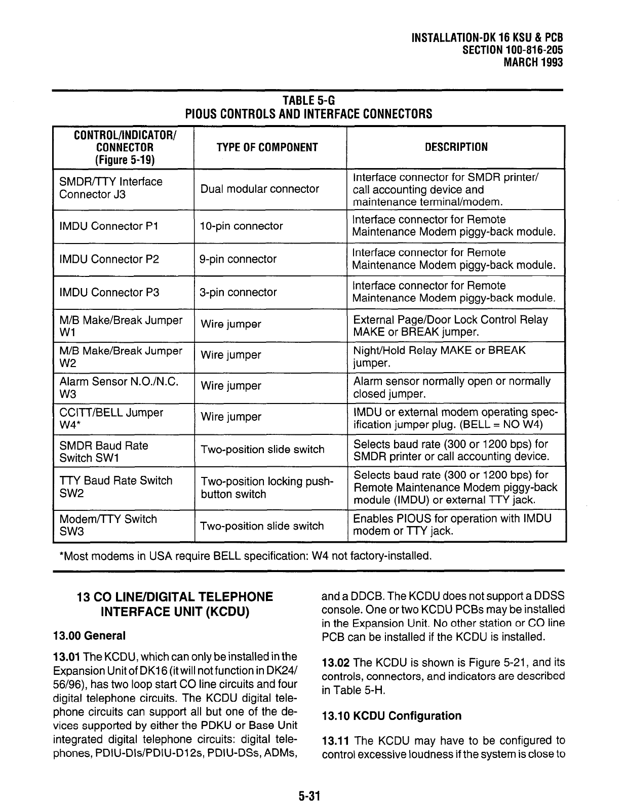
TABLE 5-G
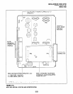
PIOUS CONTROLS AND INTERFACE CONNECTORS
CONTROL/INDICATOR/
CONNECTOR
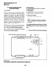
(Figure 5-19)
TYPE OF COMPONENT
DESCRIPTION
SMDR/TTY Interface
Connector J3
Dual modular connector
Interface connector for SMDR printer/
call accounting device and
maintenance terminal/modem.
IMDU Connector PI 1 O-pin connector
Interface connector for Remote
Maintenance Modem piggy-back module.
IMDU Connector P2 g-pin connector
Interface connector for Remote
Maintenance Modem piggy-back module.
IMDU Connector P3
3-pin connector
Interface connector for Remote
Maintenance Modem piggy-back module.
M/B Make/Break Jumper
Wire jumper
External Page/Door Lock Control Relay
Wl
MAKE or BREAK jumper.
M/B Make/Break Jumper
Wire jumper
Night/Hold Relay MAKE or BREAK
w2
jumper.
Alarm Sensor N.O./N.C.
Wire jumper
Alarm sensor normally open or normally
w3
closed jumper.
CCITT/BELL Jumper
Wire jumper
IMDU or external modem operating spec-
w4*
ification jumper plug. (BELL = NO W4)
SMDR Baud Rate
Two-position slide switch
Selects baud rate (300 or 1200 bps) for
Switch SW1
SMDR printer or call accounting device.
TTY Baud Rate Switch Two-position locking push-
Selects baud rate (300 or 1200 bps) for
SW2
button switch
Remote Maintenance Modem piggy-back
module (IMDU) or external TTY jack.
Modem/TTY Switch
SW3
Two-position slide switch
Enables PIOUS for operation with IMDU
modem or TTY jack.
*Most modems in USA require BELL specification: W4 not factory-installed.
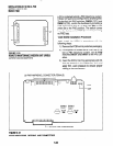
13 CO LINE/DIGITAL TELEPHONE
INTERFACE UNIT (KCDU)
13.00 General
13.01
The KCDU, which can only be installed in the
Expansion Unit of DK16 (it will not function in DK24/
56/96), has two loop start CO line circuits and four
digital telephone circuits. The KCDU digital tele-
phone circuits can support all but one of the de-
vices supported by either the PDKU or Base Unit
integrated digital telephone circuits: digital tele-
phones, PDIU-Dls/PDIU-Dl2s, PDIU-DSs, ADMs,
and a DDCB. The KCDU does not support a DDSS
console. One or two KCDU PCBs may be installed
in the Expansion Unit. No other station or CO line
PCB can be installed if the KCDU is installed.
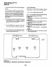
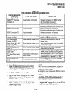
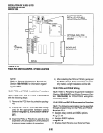
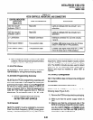
13.02 The KCDU is shown is Figure 5-21, and its
controls, connectors, and indicators are described
in Table 5-H.
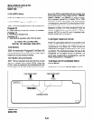
13.10 KCDU Configuration
13.11
The KCDU may have to be configured to
control excessive loudness if the system is close to
5-31