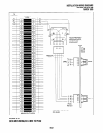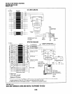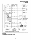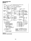
INSTALLATION-WIRING DIAGRAMS
SECTION lOO-816-208
MARCH1993
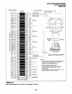
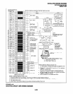
TO PSTU
W/FEMALE CONNECTOR BRIDGING A
JACKETED TWISTED STATION CABLE
/\I’
24 AWG
SUPPORT BGM)
NOT USED
MODULAR
CORD
R6
1
NOT USED
T7
R7
TIP 1 1 RING
STANDARD TELEPHONE,
VOICE MAIL PORT, OR
SIMILAR DEVICE
39
1
NOT USED
T8 (ckt8CAN
R8 SUPPORT
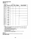
NOTES:
1. All cable 24 A WG; max loop resistance -
BGM)
300 ohms from PSTU to standard
telephone/I/M port.
2. Standard telephones may be on- or
off-premises. Off-premises connection
is made via OL 13A F/C, and RJ2 1 X jack.
3. Connect up to two telephone ringers
to each Tip and Ring pair.
4. WI, ring voltage option;
L = 13ov P-P
H = 19OV P-P
5. Two ringers maximum per port, “H” or “L”
position.
NOT USED
66M150 SPLIT BLOCK ’
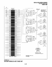
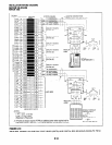
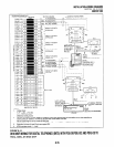
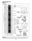
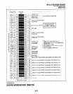
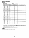
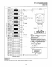
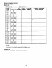
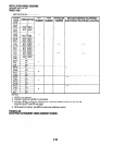
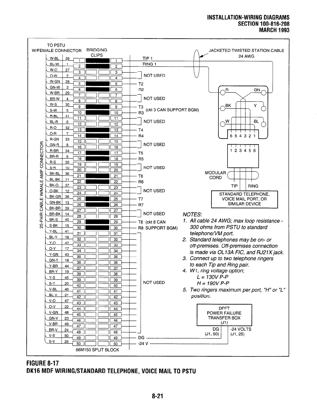
FIGURE 8-17
DK16 MDF WIRING/STANDARD TELEPHONE, VOICE MAIL TO PSTU
8-21


