


INSTALLATION-DK 16 KSU & PCB
SECTION 100-816-205
MARCH 1993
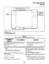
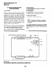
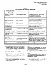
TABLE 5-D
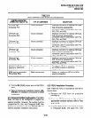
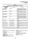
PESU CONTROLS AND INTERFACE CONNECTORS
CONTROL/INDICATOR/
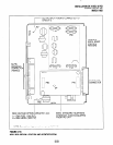
CONNECTOR (Figure 5-16)
TYPE OF COMPONENT DESCRIPTION
Off-hook Call
Announce PlO
Off-hook Call
Announce P20
Off-hook Call
Announce P40
Off-hook Call
Announce P50
Off-hook Call
Announce P60
Ring Voltage Jumper
Plug P90
1 O-pin connector
1 O-pin connector
1 O-pin connector
1 O-pin connector
1 O-pin connector
Three-terminal jumper
Interface connector for optional Off-hook
Call Announce subassembly
connector (used in conjunction with P20,
P40, P50, and P60).
Interface connector for optional Off-hook
Call Announce subassembly
connector (used in conjunction with Pl 0,
P40, P50, and P60).
Interface connector for optional Off-hook
Call Announce subassembly
connector (used in conjunction with Pl 0,
P20, P50, and P60).
Interface connector for optional Off-hook
Call Announce subassembly
connector (used in conjunction with PlO,
P20, P40, and P60).
Interface connector for optional Off-hook
Call Announce subassembly
connector (used in conjunction with Pl 0,
P20, P40, and P50).
Sets ring generator voltage level for
circuits 1 and 2.
H = 19OV P-P (factory setting)
L = 130v P-P
BGM W7 Jumper Pack White jumper wire
When cut, configures PESU, circuit 8,
for BGM source connection.
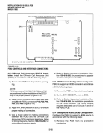
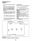
3) Apply firm, even pressure to the EOCU to
ensure proper mating of connectors.
4) Use 3-pair cable for connecting the PESU and
the OCA electronic telephone (refer to Wiring
Diagrams, Section 100-816-208, for wiring/
interconnecting details).
5) Refer to Station Apparatus Installation, Sec-
tion 100-816-206, for procedures to add OCA
to electronic telephones.
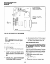
10.13 Background Music (BGM) Configura-
tion.
Configure the PESU to support a BGM source
in accordance with the following steps:
1) Remove the PCB from its protective packag-
ing.
2) Cut the W7 (BGM) jumper wire on the PESU
PCB.
3) Referto Peripherals Installation, Section
lOO-
816-207,
for BGM installation procedures.
10.14 External Amplifier Configuration.
The
PESU does not have to be configured to support an
5-24