


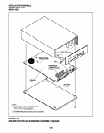
INSTALLATION-PERIPHERALS
SECTiON lOO-816-207
MARCH1993
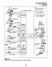
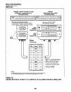
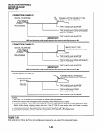
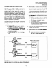
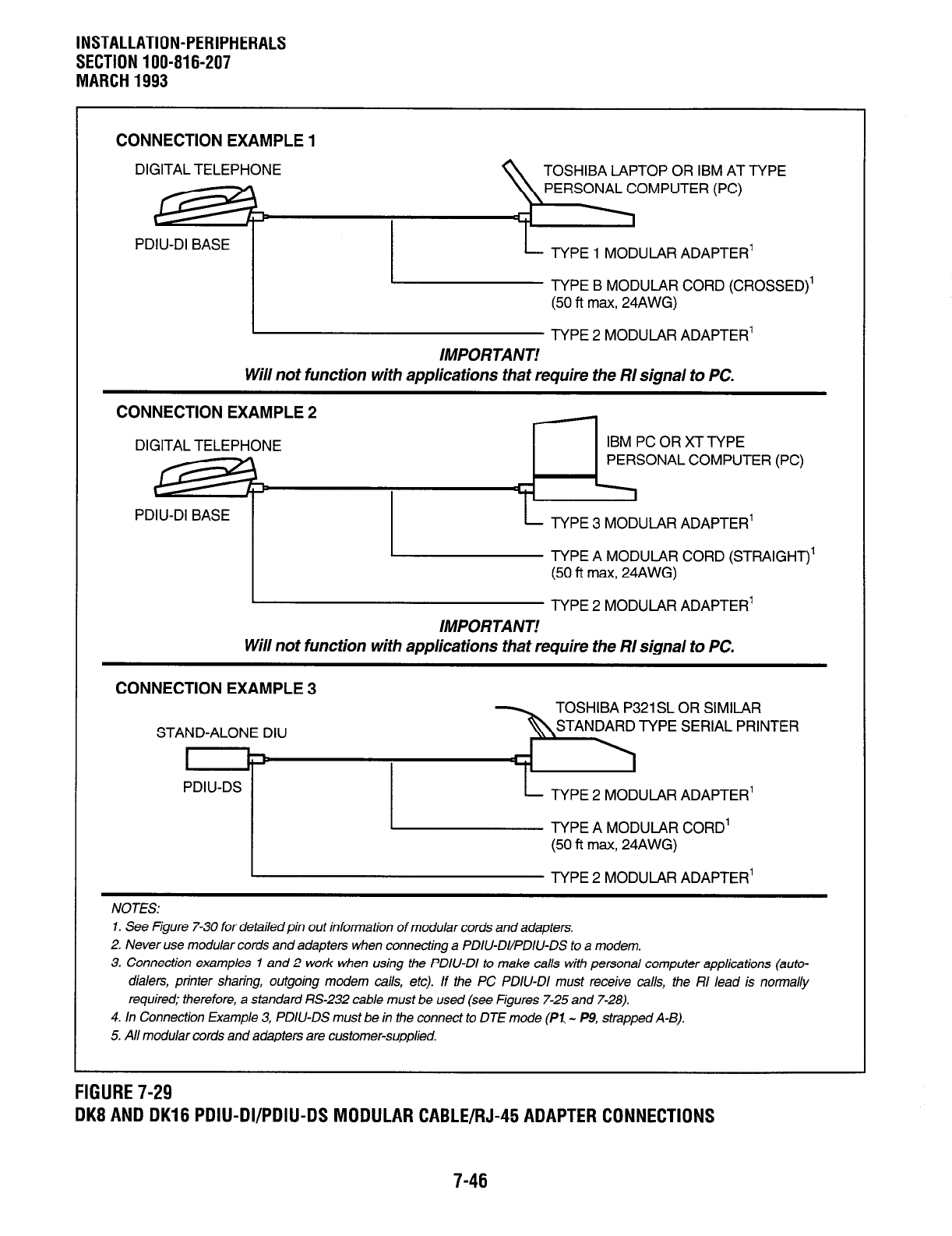
CONNECTION EXAMPLE 1
DIGITAL TELEPHONE TOSHIBA LAPTOP OR IBM AT TYPE
PERSONAL COMPUTER (PC)
PDIU-DI BASE
TYPE 1 MODULAR ADAPTER’
TYPE B MODULAR CORD (CROSSED)’
(50 fl max, 24AWG)
TYPE 2 MODULAR ADAPTER’
IMPORTANT!
Will not function with applications that require the RI signal to PC.
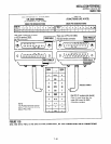
CONNECTION EXAMPLE 2
DIGITAL TELEPHONE
IBM PC OR XT TYPE
PERSONAL COMPUTER (PC)
PDIU-DI BASE
TYPE 3 MODULAR ADAPTER’
TYPE A MODULAR CORD (STRAIGHT)’
(50 ft max, 24AWG)
TYPE 2 MODULAR ADAPTER’
IMPORTANT!
Will not function with applications that require the RI signal to PC.
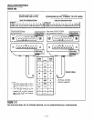
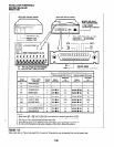
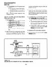
CONNECTION EXAMPLE 3
STAND-ALONE DIU
I
PDIU-DS
TOSHIBA P321 SL OR SIMILAR
STANDARD TYPE SERIAL PRINTER
TYPE 2 MODULAR ADAPTER’
TYPE A MODULAR CORD’
(50 ft max, 24AWG)
TYPE 2 MODULAR ADAPTER’
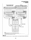
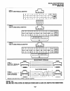
NOTES:
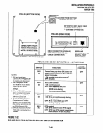
1. See Figure 7-30 for detailed pin out information of modular cords and adapters.
2. Never use modular cords and adapters when connecting a PDIU-DI/PDIlJ-DS to a modem.
3. Connection examples 1 and 2 work when using the PDIU-DI to make calls with personal computer applications (auto-
dialers, printer sharing, outgoing modem calls, etc). If the PC PDIU-DI must receive calls, the RI lead is normally
required; therefore, a standard RS-232 cable must be used (see Figures 7-25 and 7-28).
4. In Connection Example 3, PDIU-DS must be in the connect to DTE mode (PI - P9, strapped A-B).
5. All modular cords and adapters are customer-supplied.
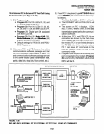
FIGURE 7-29
DK8 AND DK16 PDIU-DI/PDIU-DS MODULAR CABLE/RJ-45 ADAPTER CONNECTIONS
7-46