


PART II. DK16 PRINTED CIRCUIT BOARD
INSTALLATION
4 GENERAL
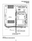
4.01 This chapter provides procedures for installa-
tion of STRATA DK16 system printed circuit boards
(PCBs) into the Base and Expansion units. This
includes installation instructions, optional configu-
ration information, and wiring and programming
considerations for each PCB.
4.02 Be sure the power supply has been tested,
and the ground has been checked. (See Chapter 5,
Section I for the power supply and Chapter 3 for
grounding.)
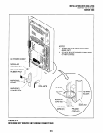
4.03 It is recommended to install the Base Unit
option PCBs K4RCU and/or KSTU before mount-
ing the Base KSU on the wall.
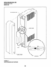
4.04 Begin Expansion PCB installation only after
completion of Expansion Unit installation (see
Chapter 5, Section I).
5 DK16 PCB INSTALLATION
CONSIDERATIONS
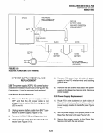
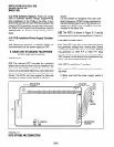
5.01 The STRATA DK16 Base Unit comes stan-
dard with eight digital telephone circuits (ports) and
four CO line circuits. The digital circuits are inte-
grated into the motherboard, and the CO line cir-
cuits are on the KCOU which is attached to the P6
and P7 connectors on the motherboard. The com-
mon control unit, like the digital telephone circuits,
is built into the motherboard.
5.10 DK16 Base Unit PCBs
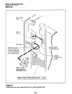
5.11 The Base Unit can support an optional KSTU
printed circuit board (PCB) which provides four stan-
dard telephone circuits (ports). In addition, a K4RCU
PCB can be installed to receive DTMF tones, and
detect busy tone for Automatic Busy Redial (ABR)
operation.
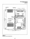
5.20 DK16 Expansion Unit PCBs
5.21 The Expansion Unit can support a number of
PCBs: it can support a PCOU which provides four
INSTALLATION-DK 16 KSU & PCB
SECTION 100-816-205
MARCH 1993
CO line circuits; one or two KCDUs which provide
two CO line circuits and four digital telephone
circuits (ports); a PDKU which provides eight digital
telephone circuits (ports); a PEKU which provides
eight electronic telephone circuits (ports); a PESU
which provides two standard and four electronic
telephone circuits (ports); a PSTU which provides
eight standard telephone circuits (ports); and a
PIOU or PIOUS which both provide a port for a
Station Message Detail Recording (SMDR) device,
an interface for remote maintenance, and relay
control options.
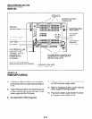
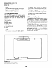
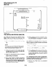
5.22 The DK16 Expansion Unit does not come from
the factory with any PCBs installed. Any of the
PCBs listed above can fit into any of the unit’s four
universal slots; however, it is recommended that
PCBs that support electronic or digital telephones
be installed into Slots 04 and 05, because Slots 06
and 07 cannot support Off-hook Call Announce or
Data Interface Units (DIUs).
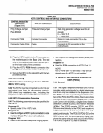
Recommended PCB slot assignments:
KCDU - Slot 04 and 05 (2 maximum)
PDKU, PEKU, PESU, PSTU - Slot 04 (1 maxi-
mum, cannot be installed with KCDU.)
PCOU - Slot 05 (1 maximum, cannot be in-
stalled with KCDU.)
PIOU/PIOUS - Slot 06 (1 maximum)
5.30 PCB Option Considerations
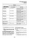
5.31 PCBs may be configured for a variety of
hardware and software options. Hardware options
are defined as either internal (generally related to
optional PCB subassemblies) or external (related
to connection of peripheral equipment such as
background music, voice mail, etc). Hardware and
software options for each PCB are identified in the
individual PCB installation procedures in this chap-
ter.
5.32 PCB Hardware Options. Each PCB must be
configured for the applicable hardware options
prior to installation of the PCB. Configuration in-
structions for internal hardware options are pro-
vided in the individual PCB installation procedures
in this chapter. Configuration instructions for exter-
nal hardware options are provided in Peripheral
Installation, Section 100-816-207.
5-13