


INSTALLATION-SITE REQUIREMENTS
SECTION 100-816-202
MARCH 1993
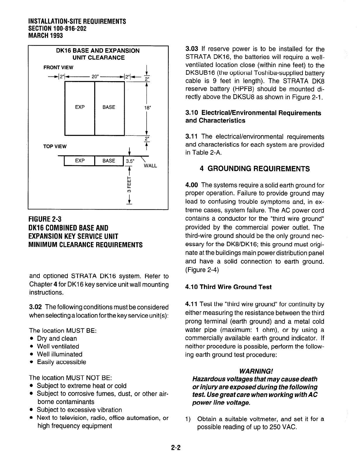
DK16 BASE AND EXPANSION
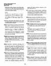
UNIT CLEARANCE
FRONT VIEW
-4 2+----- 20” ------4 2”+- 2”
TOP VIEW
t
I
EXP BASE
3.5” \
WALL
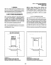
FIGURE 2-3
DK16 COMBINED BASE AND
EXPANSION KEY SERVICE UNIT
MINIMUM CLEARANCE REQUIREMENTS
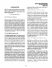
and optioned STRATA DK16 system. Refer to
Chapter 4 for DK16 key service unit wall mounting
instructions.
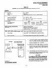
4.00 The systems require a solid earth ground for
proper operation. Failure to provide ground may
lead to confusing trouble symptoms and, in ex-
treme cases, system failure. The AC power cord
contains a conductor for the “third wire ground”
provided by the commercial power outlet. The
third-wire ground should be the only ground nec-
essary for the DK8/DK16; this ground must origi-
nate at the buildings main power distribution panel
and have a solid connection to earth ground.
(Figure 2-4)
4.10 Third Wire Ground Test
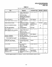
3.02 The following conditions must be considered
when selecting a location forthe key service unit(s):
The location MUST BE:
l
Dry and clean
l
Well ventilated
l
Well illuminated
l
Easily accessible
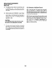
4.11 Test the “third wire ground” for continuity by
either measuring the resistance between the third
prong terminal (earth ground) and a metal cold
water pipe (maximum: 1 ohm), or by using a
commercially available earth ground indicator. If
neither procedure is possible, perform the follow-
ing earth ground test procedure:
WARNING!
The location MUST NOT BE:
Hazardous voltages that may cause death
l
Subject to extreme heat or cold
or injury are exposed during the folio wing
l
Subject to corrosive fumes, dust, or other air-
test. Use great care when working with AC
borne contaminants
power line voltage.
l
Subject to excessive vibration
l
Next to television, radio, office automation, or
high frequency equipment
1) Obtain a suitable voltmeter, and set it for a
possible reading of up to 250 VAC.
3.03 If reserve power is to be installed for the
STRATA DK16, the batteries will require a well-
ventilated location close (within nine feet) to the
DKSUB16 (the optional Toshiba-supplied battery
cable is 9 feet in length). The STRATA DK8
reserve battery (HPFB) should be mounted di-
rectly above the DKSU8 as shown in Figure 2-l.
3.10 Electrical/Environmental Requirements
and Characteristics
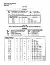
3.11 The electrical/environmental requirements
and characteristics for each system are provided
in Table 2-A.
4 GROUNDING REQUIREMENTS
2-2