


INSTALLATION-OK16 KSU & PCB
SECTION lOO-816-205
MARCH 1993
13)
14)
15)
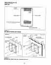
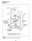
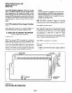
Knock out the tab on the bottom of the side
cover.
Plug the AC power cable into an outlet and
then turn ON the power supply switch.
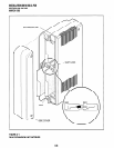
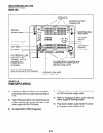
Install the side cover to the Expansion Key
Service Unit (Figure 5-7).
2.40 Reserve Power/Power Failure Options
2.41 The STRATA DK systems offer two options
to protect system operation in the event of a power
failure; the Reserve Power option (Paragraph 2.42-
2.44), and the Power Failure Emergency Transfer
option (Paragraph 17).
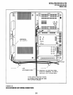
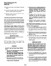
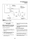
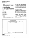
2.42 Reserve Power Option STRATA DK16
system power supply provides the capability of
connecting a reserve power source (two customer
supplied 12-volt batteries) to ensure uninterrupted
system operation in the event of a power failure. A
pre-assembled interface cable for installation of
the Reserve Power option is available from Toshiba
(PBTC-3M), refer to Figure 5-9.
IMPORTANT NOTE!
Local ordinances may dictate battery type
and installation details.
2.43 The batteries require a well-ventilated loca-
tion close (within 9 feet) to the system -the
interface cable is 9 feet long.
WARNING!
To reduce the risk of fire or injury to
persons, read and follow these instruc-
tions:
1.
2.
3.
Use only the following type and size
batteries: 12-volt, gelcell.
Do not dispose of the batteries in a fire.
The cells may explode. Check with
local codes for possible special dis-
posal instructions.
Do not open or mutilate the batteries.
Released electrolyte is corrosive and
may cause damage to the eyes or skin.
It may be toxic if swallowed.
4. Exercise care in handling batteries in
order not to short the battery with con-
duction materials such as rings,
bracelets, and keys. The battery or
conductor may overheat and cause
burns.
5. Charge the batteries provided with or
identified for use with this product
only in accordance with the instruc-
tions and limitations specified in this
manual.
6. Observe proper polarity orientation
between the batteries and battery
charger.
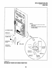
2.44 Reserve Power Installation. Install the Re-
serve Power option in accordance with the follow-
ing steps (refer to Figure 5-9):
1) Connect the PBTCSM black jumper wire from
the positive terminal of one 12VDC battery to
the negative terminal of the second 12VDC
battery.
2) Ensure that a serviceable 1 O-ampere fuse is
installed in the in-line fuse holder of the PBTC-
3M battery cable.
3) Connect the white lead of the PBTCSM
battery cable to the open positive terminal of
the 12VDC battery. Connect the black lead to
the open negative terminal of the second
12VDC battery.
IMPORTANT NOTE!
The KSU must be connected to the live
operating (HOT) AC power source, and
the power supply ON/OFF switch set to
ON prior to the final step of connecting the
reserve power batteries to the power sup-
ply via the BATT +/- receptacle. If the
batteries are connected affer ACpower is
lost, reserve power will not function.
4)
5)
Connect the PBTC-3M battery cable two-
prong male plug to the power supply BATT +/
- receptacle.
To test reserve power operation, disconnect
the system AC power plug with the power
supply power ON/OFF switch in the ON po-
sition. The system should continue to operate
without any interruption.
5-10