


INSTALLATION-OK8 KSU & PC8
SECTION 100-816-204
MARCH 1993
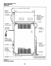
2.20 Mounting the Key Set-vice Unit
1) Make sure the power supply switch is turned
OFF.
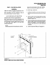
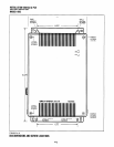
2) Place the Key Service Unit on the desired
location on the mounting surface and markthe
location of the four screw holes (there is one on
each corner). See Figures 4-1 and 4-2.
NOTE:
Make sure the location of the Key Service
Unit meets the minimum clearance require-
ments specified in Figure 2- 1 in Chapter 2.
3)
4)
5)
6)
7)
8)
Drill holes on these marks.
Secure screws approximately two thirds of the
way into the top two holes on the mounting
surface.
Hang the unit from the top two screws and
then secure the screws completely into the
mounting surface.
Finish securing the unit to the mounting sur-
face by completely screwing the bottom two
screws into the wall.
Ground system according to Chapter 2, Para-
graph 4.
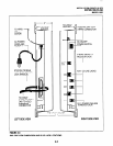
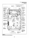
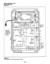
Connect applicable wiring (modular CO line
cords, 25-pairamphenol connectorcable, etc.)
to the Key Service Unit. Route the wiring as
shown in Figure 4-4, and then fasten wiring to
the unit with the tie wraps that come with the
Key Service Unit. (See Section 100-8-l 6-208,
for additional wiring information.)
NOTE:
Figure 4-4 shows cables routed to the right;
they may a/so be routed to the left, depending
on the location of the MDF.
9)
10)
11)
If the Reserve Power Battery and Charger
(HPFB) is going to be installed, refer now to
Paragraph 2.30. If not, proceed to Step 10.
Plug the AC power cable into an outlet and
then turn ON the DC power supply switch.
Reinstall the front cover onto the Key Service
Unit.
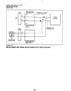
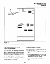
2.30 Installing the Reserve Power Battery
and Charger (HPFB) (Figure 4-4)
1)
2)
3)
4)
5)
6)
Place the HPFU directly above the DK8 KSU.
Mark the location of the two screw holes, then
drill holes.
Screw the two screws two-thirds into the
mounting surface.
Hang the HFPU on the screws then tighten the
screws into the mounting surface.
Plug the first HPFU connector into BATT con-
nector on the right side of the KSU.
Connect a ground wire from the HPFB “FG”
screw to the DK8 QPSU8 screw labeled
“HPFBG.” The ground wire can be fed through
the opening by the AC power cord (see Figure
4-3).
NOTE:
The DK8 should be plugged into AC power
and the DC power switch should be turned
on. The HFPU will not start to operate if AC
power is not available during the initial instal-
la tion.
7) The 24V LED on the HPFU should light. If it
does not light, press the battery OFF switch
with a pencil point or other small-tipped object.
8) Dress and tie-wrap the HPFU cables per Fig-
ure 4-4.
9) To mount a second HPFU, repeat steps 1-4,
then plug the second HPFU connector in the
first HPFU and connect an FG wire between
each HPFB FG screw.
10) To test the HPFU, remove the DK8 AC plug
from the AC outlet. The DK8 AC LED will go
out but the DK8 DC LED remains on, also the
system remains in normal working order and
the HPFU 24V LED remains on.
11) If it is desired to turn off the HPFU (after loss
of AC power), use a pencil or other sharp
object to press the Battery Off switch.
CAUTIOM’
Once the HPFU is turned off or unplugged
(During AC power loss) it will not operate
again until AC power is restored to the
DKB KSU.
4-4