


INSTALLATION-PERIPHERALS
SECTION 100-816-207
MARCH 1993
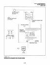
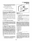
2) Screw a 1.25-inch panhead wood screw into
the mounting surface, use wall anchors if
mounting to drywall surface.
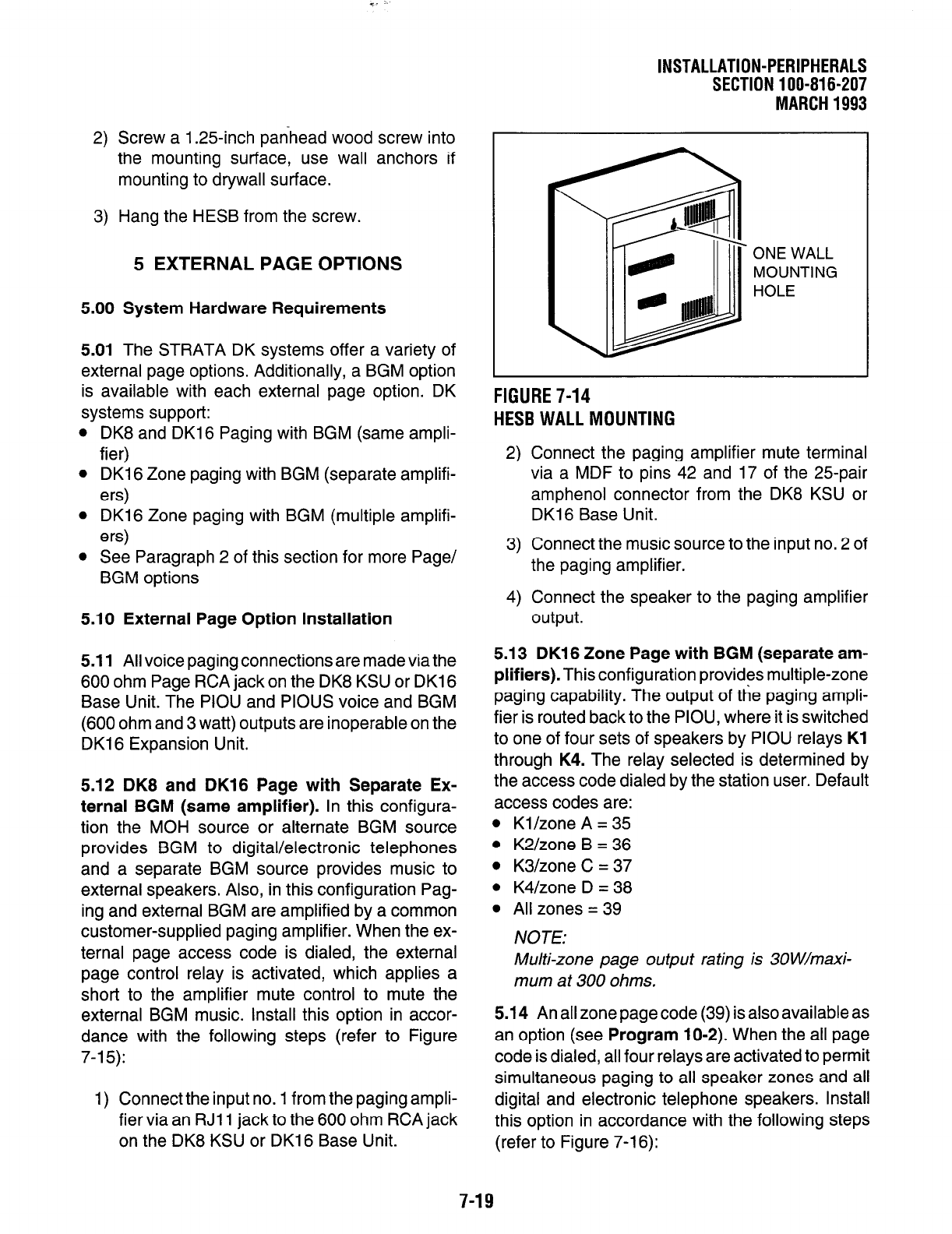
3) Hang the HESB from the screw.
5 EXTERNAL PAGE
OPTIONS
5.00 System Hardware Requirements
5.01 The STRATA DK systems offer a variety of
external page options. Additionally, a BGM option
is available with each external page option. DK
systems support:
l
DK8 and DK16 Paging with BGM (same ampli-
fier)
l
DKI 6 Zone paging with BGM (separate amplifi-
ers)
l
DK16 Zone paging with BGM (multiple amplifi-
ers)
l
See Paragraph 2 of this section for more Page/
BGM options
5.10 External Page Option Installation
5.11 All voice paging connections are made via the
600 ohm Page RCA jack on the DK8 KSU or DK16
Base Unit. The PIOU and PIOUS voice and BGM
(600 ohm and 3 watt) outputs are inoperable on the
DK16 Expansion Unit.
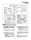
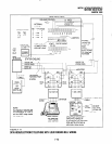
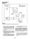
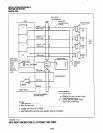
5.12 DK8 and DK16 Page with Separate Ex-
ternal BGM (same amplifier). In this configura-
tion the MOH source or alternate BGM source
provides BGM to digital/electronic telephones
and a separate BGM source provides music to
external speakers. Also, in this configuration Pag-
ing and external BGM are amplified by a common
customer-supplied paging amplifier. When the ex-
ternal page access code is dialed, the external
page control relay is activated, which applies a
short to the amplifier mute control to mute the
external BGM music. Install this option in accor-
dance with the following steps (refer to Figure
7-l 5):
1) Connect the input no. 1 from the paging ampli-
fier via an RJl 1 jack to the 600 ohm RCA jack
on the DK8 KSU or DK16 Base Unit.
ONE WALL
MOUNTING
HOLE
FIGURE 7-14
HESB WALL MOUNTING
2) Connect the paging amplifier mute terminal
via a MDF to pins 42 and 17 of the 25pair
amphenol connector from the DK8 KSU or
DK16 Base Unit.
3) Connect the music source to the input no. 2 of
the paging amplifier.
4) Connect the speaker to the paging amplifier
output.
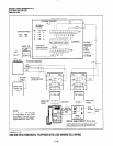
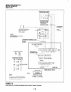
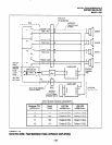
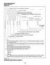
5.13 DKI 6 Zone Page with BGM (separate am-
plifiers). This configuration provides multiple-zone
paging capability. The output of the paging ampli-
fier is routed back to the PIOU, where it is switched
to one of four sets of speakers by PIOU relays Kl
through K4. The relay selected is determined by
the access code dialed by the station user. Default
access codes are:
l
Kl/zone A = 35
l
K2/zone B = 36
l
K3/zone C = 37
l
K4/zone D = 38
l
All zones = 39
NOTE:
Multi-zone page output rating is 3OW/maxi-
mum at 300 ohms.
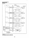
5.14 An all zone page code (39) is also available as
an option (see Program 10-2). When the all page
code is dialed, all four relays are activated to permit
simultaneous paging to all speaker zones and all
digital and electronic telephone speakers. Install
this option in accordance with the following steps
(refer to Figure 7-l 6):
7-19